Snowmobile Ski Doo REV SERIES (2004 year). Manual - part 68


  Index      Snowmobiles / ATV     Snowmobile Ski Doo REV SERIES - service manual 2004 year


Search            


Content   ..  66  67  68  69   ..


Snowmobile Ski Doo REV SERIES (2004 year). Manual - part 68


Section 07 ELECTRICAL SYSTEM
Subsection 04 (ELECTRIC STARTER)

REMOVAL

– Disconnect BLACK (-) cable from battery.
– Disconnect RED (+) cable from battery.

WARNING

Always disconnect BLACK (-) cable first and
connect last.

– Remove tuned pipe.
– Disconnect RED cable from starter.
– Disconnect ground cable from starter.
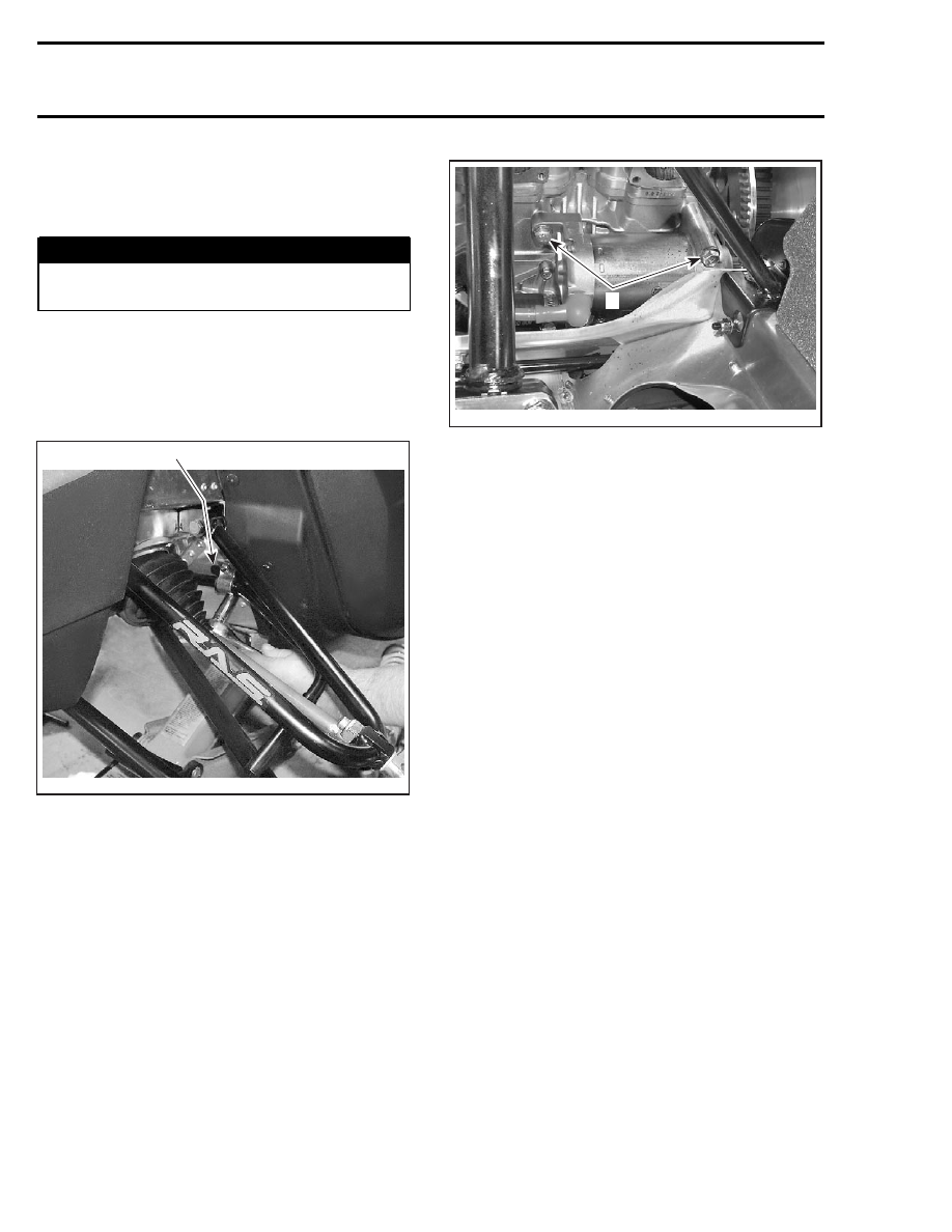
– Remove stabilizer bar clamp to access the

lower starter retaining bolt.

1

A33F27B

1. Clamp

– Unbolt and remove starter from engine.

A33E0VA

1

1. Bolts to be removed

DISASSEMBLY

Before disassembling, trace index marks on
starter housing no. 10 and starter housing assem-
bly no. 8 to ease further assembly.

Remove starter through bolts no. 17. Separate
end frame housing no. 14 from starter housing
no. 10. Withdraw starter housing from armature
no. 11.

Brush holder no. 13 can be removed from end
frame housing no. 14 by disconnecting the end
frame attached brush from brush holder no. 13.

Check the radial play between the armature shaft
and end frame bearing. Replace the end frame
bearing or replace starter. If parts are in good con-
dition then coat with synthetic grease (P/N 413
711 500) before reinstalling them.

Push back the collar no. 3 using a screwdriver.

Remove snap ring no. 2. Remove collar no. 3 and
spring no. 4.

264

mmr2004-Rev

Section 07 ELECTRICAL SYSTEM

Subsection 04 (ELECTRIC STARTER)

A32E20A

2

1

1. Collar
2. Snap ring

Turn starter clutch no. 6 clockwise to remove it
from armature assembly no. 11.

Pull housing from armature.

CLEANING

CAUTION: Yoke assembly and drive unit as-
sembly must not be immersed in cleaning sol-
vent.

Clean brushes and holders with a clean cloth
soaked in solvent. Brushes must be dried thor-
oughly with a clean cloth.

Blow brush holders clean using compressed air.

WARNING

Always wear safety glasses when using com-
pressed air.

Remove dirt, oil or grease from commutator using
a clean cloth soaked in suitable solvent. Dry well
using a clean and dry cloth.

Clean engine ring gear teeth and drive unit (clutch).

NOTE: Bushings or bearings must not be cleaned
with grease dissolving agents.

Immerse all metal components in cleaning solu-
tion. Dry using a clean and dry cloth.

INSPECTION

All Models except 4-Tec Engines

Armature

NOTE: An ohmmeter may be used for the follow-
ing testing procedures, except for the one con-
cerning the shorted windings in the armature.

Check the commutator for roughness, burnt or
scored surface. If necessary, turn the commuta-
tor on a lathe, enough to remove grime only.

Check the commutator for mica depth. If the
depth is less than 0.20 mm (.008 in), undercut
the mica. Be sure that no burrs are left and no
copper dust remains between the segments after
the undercutting operation is completed.

F01H0RA

1

1. Commutator undercut 0.20 mm (.008 in)

Check the commutator out-of-round condition
with V Blocks and an indicator. If the commutator
out-of-round is more than 0.40 mm (.016 in), the
commutator should be turned on a lathe.

Check commutator outer diameter. If less than
specified value, replace.

A03E06A

MODEL

WEAR LIMIT

All models

27 mm (1.063 in)

mmr2004-Rev

265

Section 07 ELECTRICAL SYSTEM
Subsection 04 (ELECTRIC STARTER)

Test for Ground Circuit in the Armature

Use growler test probes. Check between arma-
ture core and the commutator bars. If growler
lamp turns on, bars are grounded. If so, replace
armature.

A09E08A

1

2

1. Test probes
2. Commutator bars

Test Armature for Shorted Winding

When the armature is rotated in the growler with a
steel strip (hacksaw blade) held above it, the strip
will vibrate over that area of the armature which
has short circuit. Replace armature if so.

A09E09A

1

2

1. Steel strip (hack-saw blade)
2. Growler

Test the Armature for Open Circuit

Use growler test probes. Place one test probe
on a commutator bar and the other test probe
on the neighboring bar. Repeat this operation for
all bars, moving one test probe at a time. If the
growler lamp does not turn on, the armature cir-
cuit between these 2 bars is opened. The arma-
ture should be replaced or repaired; open circuits
most often occur at the commutator riser where
coils are soldered. (Burnt commutator bars are
usually an indication of an open-circuit armature
coil).

Brush Holder

Check the brush holder for insulation using
growler test probes. Place one test probe on the
insulated brush holder and the other test probe
on the brush holder plate. If the growler lamp
turns on, the brush holder has to be repaired or
replaced.

Brush Length

Measure brush length. If less than the specified
value, replace them.

LENGTH

MODEL

NEW

WEAR LIMIT

All

10 mm

(.400 in)

6 mm

(.236 in)

A03E05A

1

2

TYPICAL
1. New
2. Wear limit

End Housing

Check the mica insulation of the positive brush
and also the roller bearing condition. Replace, if
necessary.

266

mmr2004-Rev

Section 07 ELECTRICAL SYSTEM

Subsection 04 (ELECTRIC STARTER)

1

2

A32E22A

1. Roller bearing
2. Positive brush

Overrunning Clutch

The pinion of the overrunning clutch should turn
smoothly in a clockwise direction, and should not
slip in a counterclockwise direction. If defective,
replace.

Check the pinion teeth for wear and damage. If
defective, replace.

Relay

Inspect connections and clean as necessary. Re-
lay condition can be checked with an ohmmeter.
Install test probes on large connectors of relay
when it is activated (+ on RED/GREEN wire and
- on relay body for the fan cooled models and - on
the BLACK wire for liquid cooled models).

IMPORTANT: No current must be present on large
cables when using ohmmeter, otherwise meter
could be damaged.

ASSEMBLY

Reverse the order of disassembly to reassemble
starter. However, attention should be paid to the
following operations.

Prior to assembling, coat sliding surfaces on arma-
ture shaft splines, overrunning clutch and bushing
with synthetic grease (P/N 413 711 500).

After placing collar no. 3 on armature shaft no. 11,
fit new snap ring no. 2 on armature shaft, then
make sure that it is properly secured.

Slide collar no. 3 over snap ring no. 2 and secure
in place by punching it at two or three places.

A03E0EA

1

2

4

3

1. Armature shaft
2. Snap ring
3. Collar
4. Punch

Starter Housing Assembly and Starter Housing

Align previously traced indexing marks.

1

A32E21A

TYPICAL
1. Aligned indexing marks

Open brushes and slide over commutator.

Align end frame locating notch with yoke locating
protrusion and properly sit brush holder no. 13 into
housing no. 14.

mmr2004-Rev

267


Content   ..  66  67  68  69   ..