Snowmobile Ski Doo REV SERIES (2004 year). Manual - part 66


  Index      Snowmobiles / ATV     Snowmobile Ski Doo REV SERIES - service manual 2004 year


Search            


Content   ..  64  65  66  67   ..


Snowmobile Ski Doo REV SERIES (2004 year). Manual - part 66


Section 07 ELECTRICAL SYSTEM

Subsection 01 (IGNITION TIMING)

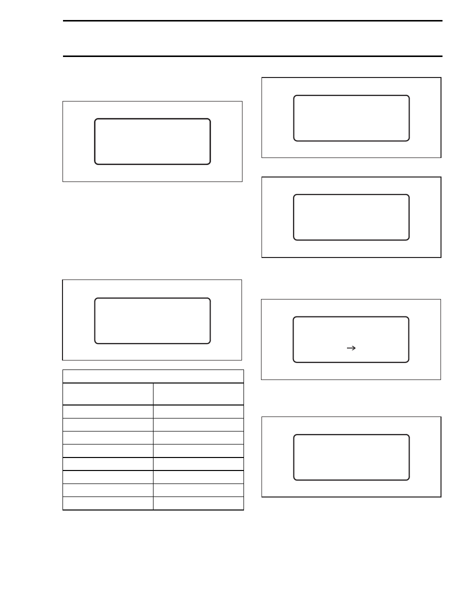
Select YES using the key

↔.

Press ENTER.

A30E23A

T I M I N G < 1 - 8 > :

T I M I N G < 1 - 8 > :

Select a timing correction factor corresponding to
correction needed.

Example: Timing mark as verified with a timing
light at 3500 RPM was too early by 2°. The cor-
rection factor programmed is no. 4.

Select correction factor no. 5. This will retard the
timing by 2° because the difference between cor-
rection factor no. 4 and no. 5 is - 2° (passing from
1° to - 1°).

A30E2HA

T I M I N G < 1 - 8 > : 5

IGNITION CORRECTION FACTOR

CORRECTION FACTOR

PROGRAMMED IN MPEM

IGNITION TIMING

CORRECTION

2

3

4

1

5

- 1°

6

- 2°

7

- 3°

8

- 4°

Press ENTER.

A30E2GA

2 .   E N G I N E   S E R I A L #

> 1 .   T I M I N G   A D J U S T

3 .   C A L I B R A T I O N

Press ENTER.

A30E24A

T I M I N G < 1 - 8 > : 5

P R E S S   A N Y   K E Y. . .

The display confirms that correction factor has
been changed to no. 5.

Press any key.

A30E27A

M O D I F Y ?

YES                          NO

If the new correction factor selected above is the
good one select NO and press ENTER. Otherwise
select YES to choose an other correction factor.

A30E2GA

2 .   E N G I N E   S E R I A L #

> 1 .   T I M I N G   A D J U S T

3 .   C A L I B R A T I O N

Press MENU.

mmr2004-Rev

255

Section 07 ELECTRICAL SYSTEM
Subsection 01 (IGNITION TIMING)

Scroll to no. 7 SAVE AND QUIT.

A30E29A

   4 .   E N G I N E   P A R A M .

5 .   H O U R   I N F O .

6 .   M P E M   I N F O .

> 7 . S A V E   +   Q U I T

Press ENTER.

A30E2AA

S A V E
M O D I F I C A T I O N S ?

                  Y E S                 N O

Press ENTER.

A00A42A

T R A N S F E R

P G M R           M P E M

During a very short period of time the following
message will appear.

A30E2BA

V E R I F Y

P G M R           M P E M

V E R I F Y

P G M R           M P E M

After the programmer has verified, following mes-
sage will appear.

O P E R A T I O N

S U C C E S S F U L L

P R E S S   A N Y   K E Y . . .

A00A3EA

Press any key.

I F   T E R M I N A T E D

Y O U   C A N   U N P L U G

P R E S S   A N Y   K E Y . . .

A00A3FA

Press any key.

   1 .   C H E C K   K E Y S

2 .   P R O G R A M   K E Y

> 3 .   V E H I C L E   I N F O

4

S T A R T   V E H .

+

A30E1XA

Unplug supply cable and 9-volt adaptor.

Recheck ignition timing with timing light when
completed.

256

mmr2004-Rev

Section 07 ELECTRICAL SYSTEM

Subsection 02 (SPARK PLUGS)

SPARK PLUGS

DISASSEMBLY

First unscrew the spark plug 1 turn.

Clean the spark plug and cylinder head with pres-
surized air, then completely unscrew.

WARNING

Whenever using compressed air,

always

wear protective eye wear.

SPARK PLUG INSTALLATION

Prior to installation make sure that contact sur-
faces of the cylinder head and spark plug are free
of grime.

CAUTION: Do not adjust electrode gap of spark
plug BR9ECS.

1) Apply anti-seize lubricant (P/N 293 800 070)

over the spark plug threads to prevent possi-
ble seizure.

2) Hand screw spark plug into cylinder head and

tighten with a torque wrench and a proper
socket.

A00E0BA

2

1

TYPICAL
1. Proper socket
2. Improper socket

SPARK PLUG TIGHTENING
TORQUE

MODEL

SPARK

PLUGS

TORQUE

N•m (lbf•ft)

All models

NGK

27 (20)

mmr2004-Rev

257

Section 07 ELECTRICAL SYSTEM

Subsection 03 (BATTERY)

BATTERY

NOTE: For manual start SDI models with a small
battery/capacitor arrangement, refer to ENGINE
MANAGEMENT SECTION.

GENERAL

Sealed valve regulated lead acid (VRLA) battery
are used. They are non-spillable and maintenance
reduced — no electrolyte level to be checked and
readjusted. No ventilation tube is attached to the
battery.

SUPPLIER P/N

BOMBARDIER P/N

YTX20L-BS

515 1756 42

REMOVAL

WARNING

Battery BLACK negative cable must always be
disconnected first and connected last.

WARNING

Never charge or boost battery while installed
on vehicle.

Open right side panel of vehicle.

Disconnect BLACK negative cable end from the
terminal.

Slide off rubber boot from RED cable and discon-
nect it.

Unscrew the bracket retaining nut and lift bracket
to remove it.

Put bracket aside.

Remove battery.

A33E0UA

1

2

3

1. Rubber boot of RED positive cable terminal
2. Bracket retaining nut
3. Battery bracket

CAUTION: Should any electrolyte spillage oc-
cur, immediately wash off with a solution of
baking soda and water to prevent damage to
vehicle components.

CLEANING

Clean the battery, battery casing, cables and bat-
tery posts using a solution of baking soda and wa-
ter.

Remove corrosion from battery cable terminals
and battery posts using a firm wire brush. Bat-
tery top should be cleaned by soft brush and any
grease-cutting soap or baking soda solution.

INSPECTION

Visually inspect battery casing for cracks, leaks or
other possible damage. Discoloration, warping or
raised top, indicates that battery has overheated
or been overcharged. If casting is damaged, re-
place battery and thoroughly clean battery tray and
close area with water and baking soda.

WARNING

Should the battery casing be damaged, wear
a suitable pair of non-absorbent gloves when
removing the battery by hand.

Inspect battery posts for security of mounting.

mmr2004-Rev

259


Content   ..  64  65  66  67   ..