Snowmobile Ski Doo REV SERIES (2004 year). Manual - part 58
Section 06 TRANSMISSION
Subsection 02 (DRIVE PULLEY)
A32D2YA
1
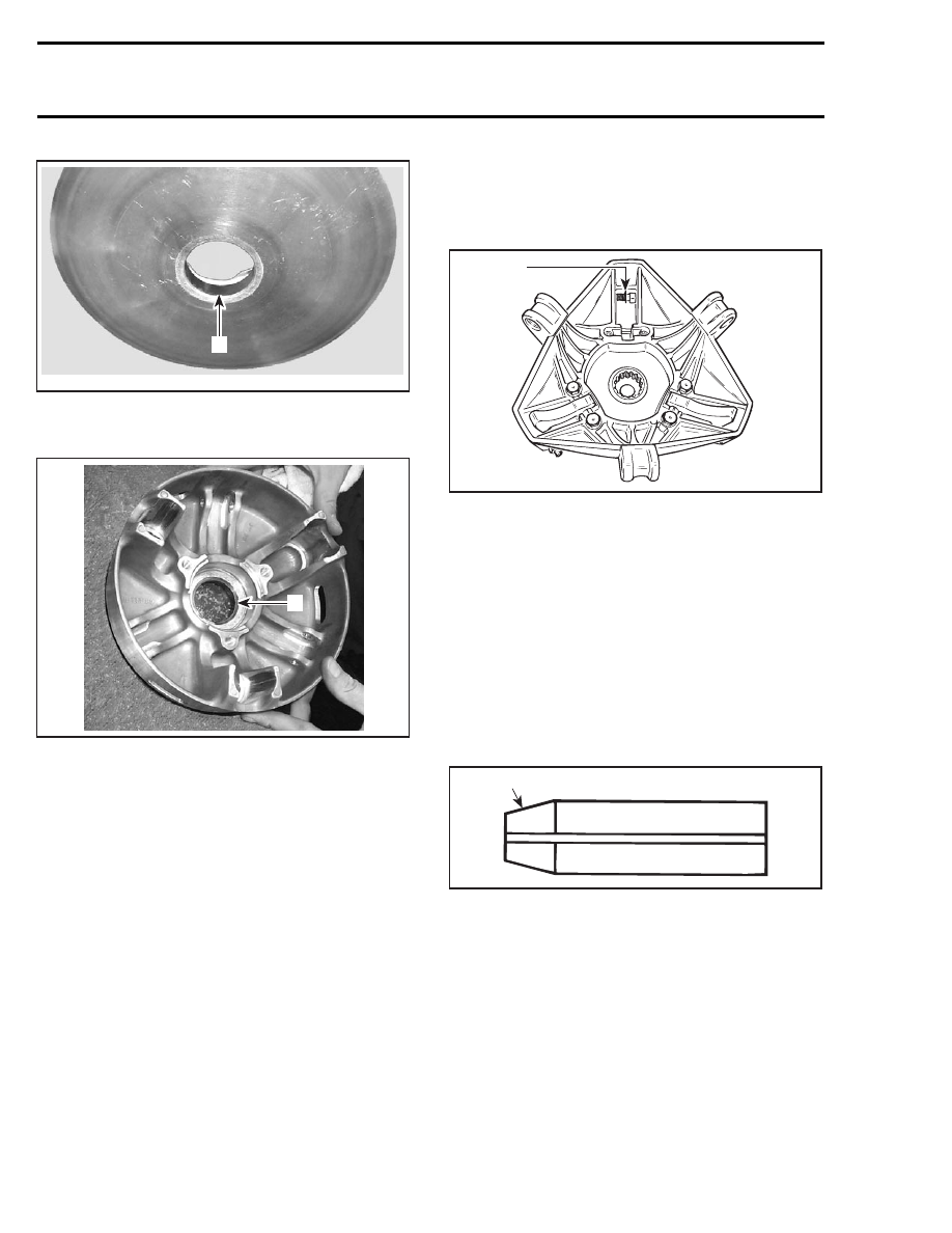
1. Bushing
Install the circlip.
1
A32D2ZA
1. Circlip
Spring Cover Bushing Replacement
Under normal use there is no need to replace this
bushing.
In case of replacement, it’s recommended to re-
place spring cover ass’y.
ASSEMBLY
NOTE: This drive pulley is lubrication free. Do not
lubricate any component.
1,2,3, Screw, Ring Gear and Loctite 271
Apply Loctite 271 (P/N 413 702 900) on threads
and then torque to 27 N•m (20 lbf•ft).
26,27,28, Calibration Screw, Washer
and Locking Nut
When installing calibration screw, make sure to
install washer as shown.
A16D07A
1
TYPICAL
1. Washer
Torque locking nut to 10 N•m (89 lbf•in).
15, Pin
Always use the same type of pin as originally in-
stalled when servicing. Different types have dif-
ferent weights for calibration purpose. Refer to
TECHNICAL DATA.
21,22,23, Screw, Dowel Tube and Ramp
Insert dowel tube from chamfered side. Make
sure ramp is centered on dowel tube.
A16D08A
1
1. Chamfered side
Position dowel tube split at the angle A.
220
mmr2004-Rev