Snowmobile Ski Doo REV SERIES (2004 year). Manual - part 52


  Index      Snowmobiles / ATV     Snowmobile Ski Doo REV SERIES - service manual 2004 year


Search            


Content   ..  50  51  52  53   ..


Snowmobile Ski Doo REV SERIES (2004 year). Manual - part 52


Section 05 2–TEC ENGINE MANAGEMENT
Subsection 02 (COMPONENT INSPECTION AND ADJUSTMENT)

Refer to TEMPERATURE SENSOR TABLE at the
beginning of this section to find the corresponding
resistance value for this sensor temperature.

If out of specification, replace the sensor.

If resistance tests good,reconnect the WTS and
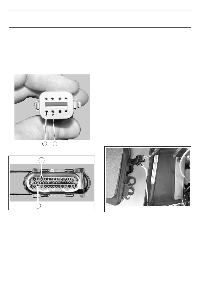
disconnect the connector A on the ECM as well
as the engine connector.

A32C9IC

6

5

ENGINE CONNECTOR

R1503motr187A

11

27

ECM CONNECTOR A

Using a multimeter, recheck resistance value
between terminals 5 and 6 on engine connector.
This resistance is used for temperature gauge.

Refer to TEMPERATURE SENSOR TABLE at the
beginning of this section to find the corresponding
resistance value for this sensor temperature.

Recheck also resistance value between terminals
11 and 27 on ECM connector A. This resistance is
used for ECM.

Refer to TEMPERATURE SENSOR TABLE at the
beginning of this section to find the corresponding
resistance value for this sensor temperature.

If resistance value is correct, try a new ECM. Refer
to ECM REPLACEMENT procedures elsewhere in
this section.

NOTE: Check if wiring harness shows any signs
of scoring prior to replace the ECM.

If resistance value is incorrect, repair the connec-
tors or replace the wiring harness between ECM
connector and the CTS.

Replacement

Drain cooling system.

Disconnect CTS connector and remove CTS.
Install the new CTS and torque to 12 N•m
(106 lbf•in).

Reinstall remaining removed parts.

Refill engine coolant and bleed cooling system.
Refer to LIQUID COOLING SYSTEM section.

AIR PRESSURE SENSOR (APS)

A33E0RA

1

INSIDE LH SIDE PANEL
1. Air pressure sensor (APS)

Ensure sensor is correctly installed on air intake si-
lencer. Otherwise, the APS could generate a fault
code. Remove sensor and check for oil or dirt on
its end and if problem persists, check the wiring
harness. Perform the following tests.

Voltage Test

Check the voltage output from ECM to the APS.

194

mmr2004-Rev

Section 05 2–TEC ENGINE MANAGEMENT

Subsection 02 (COMPONENT INSPECTION AND ADJUSTMENT)

Install the tether cord cap, turn OFF engine cut-out
switch and push START/RER button momentarily
to activate the ECM.

Disconnect plug connector from APS and connect
a voltmeter between pin 1 and 2 of wiring harness.

Voltage should be 5 V.

Check the continuity between pin 3 on APS con-
nector and pin 18 on ECM connector.

If tests are good, replace the APS.

If tests are not good, continue to check the conti-
nuity of the rest of the APS circuit on the harness.

Disconnect the connector A from the ECM.

Using a multimeter, check continuity of circuits as
per following table.

CIRCUIT NUMBER

(ECM CONNECTOR DA)

APS CONNECTOR

DA-3

PIN 1

DA-4

PIN 2

DA-18

PIN 3

If wiring harness is good, try a new ECM. Refer
to ECM REPLACEMENT procedures elsewhere in
this section.

NOTE: Check if wiring harness shows any signs
of scoring prior to replace the ECM.

Otherwise, repair the connectors or replace the
wiring harness between ECM connector and the
APS.

Replacement

Disconnect APS connector and remove the APS.
The ATS is retained with a screw.

Install the new APS.

EXHAUST GAS TEMPERATURE
SENSOR (EGTS)

A33I0JA

2

1

1. Muffler
2. Exhaust gas temperature sensor (EGTS)

Resistance Test

Disconnect the plug connector from the EGTS and
check sensor resistance.

Refer to TEMPERATURE SENSOR TABLE at the
beginning of this section to find the corresponding
resistance value for this sensor temperature.

If out of specification, replace the sensor.

If resistance tests good, reconnect the EGTS and
disconnect the connector DA on the ECM.

Using a multimeter, recheck resistance value be-
tween terminals 10 and 26.

If resistance value is correct, try a new ECM. Refer
to ECM REPLACEMENT procedures elsewhere in
this section.

NOTE: Check if wiring harness shows any signs
of scoring prior to replace the ECM.

If resistance value is incorrect, repair the connec-
tor or replace the wiring harness between ECM
connector and the EGTS.

Replacement

Disconnect EGTS connector and remove EGTS.

Apply anti-seize lubricant (P/N 293 800 070) over
EGTS threads to prevent possible seizure.

Torque the new EGTS to 45 N•m (33 lbf•ft).

Replug connector.

mmr2004-Rev

195

Section 05 2–TEC ENGINE MANAGEMENT
Subsection 02 (COMPONENT INSPECTION AND ADJUSTMENT)

KNOCK SENSOR (KS)

1

A32C9ZA

1. Knock sensor (KS)

Dynamic Test

Lift rear of vehicle off the ground and support it
with a wide-base mechanical stand.

Using the vehicle communication kit (VCK) with
the B.U.D.S. software, monitor the knock sensor
using the Faults section.

Start the engine and bring engine RPM above
6000 RPM. If no fault code occurs, the knock
sensor is good.

Otherwise, do the following.

Ensure sensor and head contact surfaces are
clean and mounting bolt and washer are correct
and properly torqued down.

Check the knock sensor circuit on wiring harness.

Disconnect the connector from knock sensor har-
ness.

Disconnect connector DA form the ECM and
check continuity of circuit as per following table.

A32C9NB

22

8

CIRCUIT NUMBER

(ECM CONNECTOR A)

KS CONNECTOR

DA-22

PIN 1

DA-8

PIN 2

If test is not good, repair the connector or replace
the wiring harness between ECM connector and
knock sensor.

Replacement

Unscrew and remove knock sensor from cylinder
head.

Clean contact surface, then install the new knock
sensor.

Torque screw to 24 N•m (18 lbf•ft).

CAUTION: Improper torque might prevent sen-
sor to work properly and lead engine to severe
damage of internal components.

Replug connector.

196

mmr2004-Rev

Section 05 2–TEC ENGINE MANAGEMENT

Subsection 02 (COMPONENT INSPECTION AND ADJUSTMENT)

E-RAVE SOLENOID

1

A32CA1A

1. E-RAVE solenoid

Resistance Test

Disconnect the solenoid connector.

Check resistance value between both terminals of
the solenoid.

The resistance value should be approximately
30

.

Voltage Test

Install

the

tether

cord

cap

and

push

the

START/RER button momentarily to activate ECM.

Battery voltage should be present on VIO-
LET/GREY wire. If test fail, fuse may be blown.

Continuity Test

BROWN/WHITE wire must show continuity be-
tween solenoid connector and pin 15 on connec-
tor DB from the ECM.

If test fail, repair connector or replace wiring har-
ness between ECM connector and solenoid.

Replacement

Remove the air intake silencer. Unplug the sole-
noid connector and all hoses.

NOTE: Mark hose locations for installation.

Remove solenoid screws then the solenoid.

For installation, reverse the removal procedure.

DOUBLE IGNITION COIL

A33I0AB

1

1. Ignition coil

NOTE: The ECM energizes the primary side of
each ignition coil individually. It can detect if the
double ignition coil is connected otherwise a trou-
ble code will appear upon starting.

Using the vehicle communication kit (VCK) with
the B.U.D.S. software, energize the ignition coil
from the Activation section.

You should hear the spark occurring. In doubt, use
an inductive spark tester or a sealed tester – avail-
able from after-market tool/equipment suppliers –
to prevent spark occurring in the engine compart-
ment. Otherwise, perform the following checks.

An ignition coil with good resistance measure-
ment can still be faulty. Voltage leak can occur
at high voltage level which is not detectable with
an ohmmeter. Replacing the ignition coil may be
necessary as a test.

Voltage Test

WARNING

When disconnecting coil from spark plug, al-
ways disconnect coil from main harness first.
Never check for engine ignition spark from
an open coil and/or spark plug in the engine
compartment as spark may cause fuel vapor
to ignite.

Disconnect the plug connector from the ignition
coil and check the voltage supplied by the battery.

mmr2004-Rev

197


Content   ..  50  51  52  53   ..