Snowmobile Ski Doo REV SERIES (2004 year). Manual - part 25


  Index      Snowmobiles / ATV     Snowmobile Ski Doo REV SERIES - service manual 2004 year


Search            


Content   ..  23  24  25  26   ..


Snowmobile Ski Doo REV SERIES (2004 year). Manual - part 25


Section 04 ENGINE

Subsection 01 (593, 593 HO, 593 HO SDI AND 793 HO ENGINE TYPES)

REMOVAL FROM VEHICLE

Vehicle and Engine Preparation

Place vehicle at workstation that will have access
to an engine-lifting hoist. Then start with initial
preparation of vehicle by doing the following.

Remove windshield.

Remove the RH side panel.

Disconnect BLACK (-) cable from battery, then the
RED (+) cable.

WARNING

Always disconnect battery or starter cables
exactly in the specified order, BLACK (-) cable
first. It is recommended to disconnect elec-
trical connections prior to disconnecting fuel
lines.

On SDI models, release the fuel pressure of the
system.

Refer to COMPONENT INSPECTION

AND ADJUSTMENT.

From the Front of Vehicle

Remove tuned pipe, refer to EXHAUST SYSTEM.

A33C26A

Remove starter.

NOTE: Remove BLACK starter cable from vehicle,
not from starter.

On right side of vehicle, do the following:

Remove muffler.

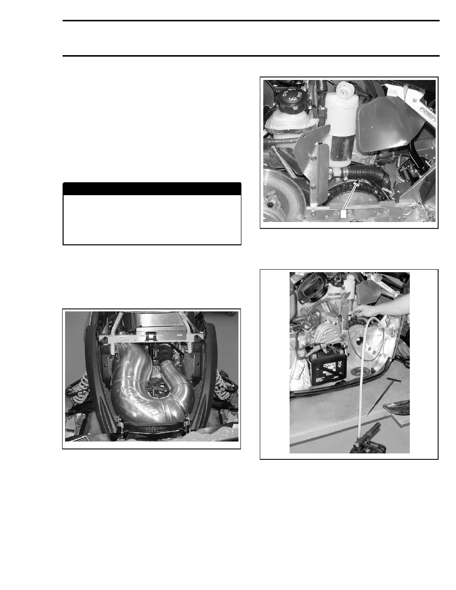
Drain coolant reservoir.

Unplug from the coolant reservoir the hose going
to the engine.

A33C27A

1

1. Coolant hose between reservoir and engine

Using pump (P/N 529 035 880), drain maximum
coolant from hose and engine.

A33C28A

Unplug magneto and trigger coil connectors.

mmr2004-Rev

81

Section 04 ENGINE
Subsection 01 (593, 593 HO, 593 HO SDI AND 793 HO ENGINE TYPES)

A33C29A

Remove rewind starter handle.

A33C2AA

Unplug heather carburetor hose from coolant
reservoir.

Unscrew oil injection reservoir then separate
coolant reservoir.

On left side of vehicle, do the following:

Remove:

– tool box
– belt guard
– belt drive
– drive pulley (refer to DRIVE PULLEY)
– air intake silencer (unplug ATS (Air Temperature

Sensor) connector).

NOTE: On SDI models, unplug APS (Air Pressure
Sensor) and ATS (Air Temperature Sensor) connec-
tors.

Separate carburetors or throttle body from engine.

Unplug coolant hose located between cylinder
head and radiator.

1

A33C2BA

1. Coolant hose between cylinder head and radiator

Remove reed valves with their gaskets.

1

A33C2CA

TYPICAL — 793 HO ENGINE TYPE SHOWN
1. Reed valve

Unplug magneto connector from MPEM.

Detach oil pump cable from oil pump.

82

mmr2004-Rev

Section 04 ENGINE

Subsection 01 (593, 593 HO, 593 HO SDI AND 793 HO ENGINE TYPES)

A33C2DA

Unplug spark plug cables.

Detach upper thermostat hose from thermostat
housing.

A33C2EA

1

1. Remove this hose

Disconnect temperature sensor connectors.

A33C2FA

Remove spark plugs and install spark plug lift ring
(P/N 529 035 830) at the farthest spark plug hole.

1

A33C18A

1. Spark plug lift ring

Remove RAVE valves.

Unscrew engine support bolts no. 1.

A33C2GA

1

LEFT SIDE OF VEHICLE
1. Engine support bolts

mmr2004-Rev

83

Section 04 ENGINE
Subsection 01 (593, 593 HO, 593 HO SDI AND 793 HO ENGINE TYPES)

A33C2HA

1

RIGHT SIDE OF VEHICLE
1. Holes to reach engine support bolts

Unscrew the engine stopper no. 2 completely.

Lift the engine a little then unplug oil pump hoses
and the crankcase vent hose.

On SDI models, disconnect all engine connectors
(CPS, WTS, KS and injectors).

Lift and slide out engine using engine removal
hook (P/N 529 035 829).

Unscrew engine support nuts no. 3 then separate
support no. 4 from engine.

INSPECTION

Check if engine support no. 4 is cracked, bent or
otherwise damaged. Replace if necessary.

Check rubber mounts no. 5 on engine support.
Replace them if brittle, cracked or otherwise dam-
aged.

INSTALLATION

To install engine in vehicle, reverse the removal
procedure. However, pay attention to the follow-
ing.

Install engine support under engine then torque
engine support nuts to 35 N•m (26 lbf•ft).

Before installing engine support bolts no. 1, apply
Loctite 243 (P/N 293 800 060) as shown in the
following illustration.

A33C2IA

A

B

A. Do not apply Loctite in this area, ± 10 mm (.39 in)
B. Loctite area, ± 8 mm (.31 in)

Torque engine support bolts to 48 N•m (35 lbf•ft).

Hand torque engine stopper no. 2 then torque its
nut no. 6 to 50 N•m (37 lbf•ft).

Reinstall all removed parts by using the appropri-
ate component/system reinstallation procedures
described in this shop.

84

mmr2004-Rev


Content   ..  23  24  25  26   ..