Snowmobile Ski Doo REV SERIES (2004 year). Manual - part 4
INTRODUCTION
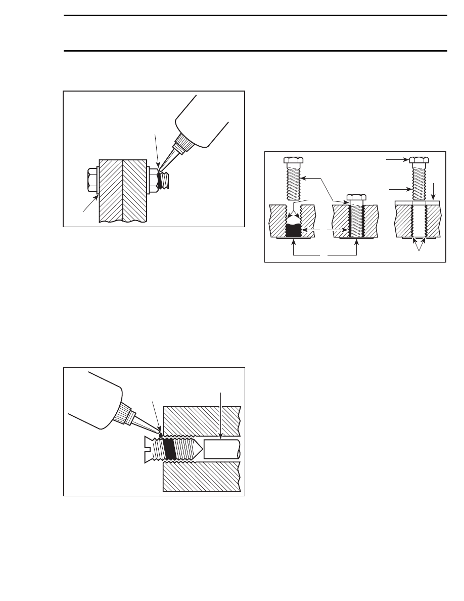
Preassembled Parts
A00A3OA
1
2
1. Apply here
2. Do not apply
– Clean bolts and nuts with solvent.
– Assemble components.
– Tighten nuts.
– Apply drops of proper strength Loctite on
bolt/nut contact surfaces.
– Avoid touching metal with tip of flask.
NOTE: For preventive maintenance on exist-
ing equipment, retighten nuts and apply proper
strength Loctite on bolt/nut contact surfaces.
Adjusting Screw
A00A3PA
1
2
1. Apply here
2. Plunger
– Adjust screw to proper setting.
– Apply drops of proper strength Loctite thread-
locker on screw/body contact surfaces.
– Avoid touching metal with tip of flask.
NOTE: If it is difficult to readjust, heat screw with
a soldering iron (232°C (450°F)).
STRIPPED THREAD REPAIR
Stripped Threads
A00A3QA
5
8
6
7
1
2
3
4
1. Release agent
2. Stripped threads
3. Form-A-Thread
4. Tape
5. Cleaned bolt
6. Plate
7. New threads
8. Threadlocker
Standard Thread Repair
– Follow
instructions
on
Loctite
FORM-A-
THREAD 81668 package.
– If a plate is used to align bolt:
– Apply release agent on mating surfaces.
– Put waxed paper or similar film on the sur-
faces.
– Twist bolt when inserting it to improve thread
conformation.
NOTE: NOT intended for engine stud repairs.
Repair of Small Holes/Fine Threads
Option 1: Enlarge damaged hole, then follow
STANDARD THREAD REPAIR procedure.
Option 2: Apply FORM-A-THREAD on the screw
and insert in damaged hole.
Permanent Stud Installation (light duty)
– Use a stud or thread on desired length.
– DO NOT apply release agent on stud.
– Do a STANDARD THREAD REPAIR.
– Allow to cure for 30 minutes.
– Assemble.
XXI