Snowmobile Arctic Cat (2008 year). Manual - part 152


  Index      Snowmobiles / ATV     Snowmobile Arctic Cat - service manual 2008 year


Search            


Content   ..  150  151  152  153   ..


Snowmobile Arctic Cat (2008 year). Manual - part 152


8-11

8

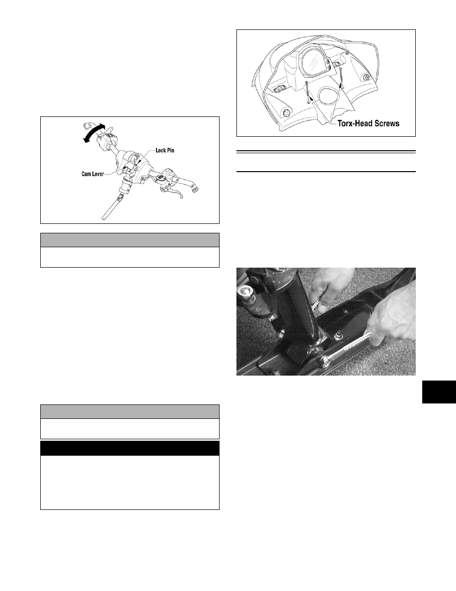
8. With the lock rod in position to the two bottom

caps and the cap springs in place, thread the cam

lever into the lock rod far enough to hold the han-

dlebar in position.

9. Depress the lock pin, lift up on the cam lever, and

swing the handlebar up and rotate to the desired

position; then press down on the cam lever until

the lock pin is properly positioned. Check steering

for maximum right/left turning capabilities.

0741-427

10. Test the handlebar to ensure that it does not rotate

within the riser block. If it does rotate, release the

cam lever and rotate the cam lever clockwise; then

press down on the cam lever until the lock pin is

properly positioned and locked. Repeat this proce-

dure until the handlebar is properly secured.

11. After the handlebar is “locked” in position, release

the cam lever and rotate it one turn clockwise; then

press down on the cam lever until it “locks” in

place.

„NOTE: At this point, gently lift the cam lever
without pressing in on the lock pin. If the cam lever
cannot be lifted, the lock pin is secure.

12. Secure the console to the steering support with the

torx-head screws and tighten the screws securely;

then close the left-side and right-side access panels

and close the hood.

741-722A

Ski

REMOVING

1. Place the front of the snowmobile on a support

stand.

2. Remove the cotter pin; then remove the slotted nut

and cap screw securing the ski assembly to the

spindle. Remove the ski. Account for the rubber

damper and washers.

AL095D

INSPECTING

„NOTE: Whenever a part is worn excessively,
cracked, or damaged in any way, replacement is
necessary.

1. Inspect the ski for cracks or deterioration.

2. Inspect the ski for abnormal bends or cracks.

3. Inspect the wear bar for wear.

4. Inspect all hardware and the spindle bushings for

wear and damage.

5. Inspect the rubber damper for damage or wear.

INSTALLING

1. Position the ski over the saddle.

! CAUTION

Do not rotate the handlebar to position that allows
air to enter the brake system.

! CAUTION

If at any time the lock pin will not engage into the
locked position, do NOT operate the snowmobile.

! WARNING

Care must be taken to securely lock the handlebar
cam lever to prevent unexpected “movement” of the
handlebar during operation over rough terrain. DO
NOT offset the handlebar so steering (maximum
right/left turning capabilities) are altered or throttle
and brake controls will be affected.

8-12

2. Apply a low-temperature grease to the non-

threaded portion of the cap screw; then slide the

cap screw (with washer as required) through the

ski and saddle accounting for the rubber damper.

„NOTE: Install the cap screw so the lock nut will
be located to the inside of the ski.

3. Apply red Loctite #271 to the threads of the cap

screw; then tighten the lock nut (with washer as

required) to 26 ft-lb.

4. Place the cotter pin into the ski cap screw and

spread the pin.

Ski Wear Bar

The ski wear bar is a replaceable bar attached to the

underside of the ski. The purpose of the wear bar is to

assist in turning the snowmobile, to minimize ski wear,

and to maintain good steering control. If the snowmo-

bile is operated primarily in deep snow, ski wear bar

wear will be minimal; however, if the snowmobile is

operated on terrain where the snow cover is minimal,

the ski wear bar will wear faster. Arctic Cat recom-

mends that the ski wear bars be checked once a week

and replaced if worn to 1/2 of original diameter.

REMOVING

1. Remove ice and snow buildup from the ski.

2. With the gas tank nearly empty (less than 1/4 full),

lay the snowmobile on its side.

3. Remove the lock nuts and washers securing the

wear bar to the ski. Account for any spacers.

0741-918

0741-917

0741-919

4. Pry the rear of the wear bar down until the wear

bar studs are clear of the ski; then slide the wear

bar rearward until the front of the wear bar is free

from the ski.

5. Remove the wear bar.

INSTALLING

1. Place spacers (if applicable) on the wear bar studs;

then insert the front of the wear bar into the hole at

the front of the ski and swing the wear bar upward.

2. Insert the wear bar studs into the holes in the ski.

3. Center the wear bar studs in the holes and install

the washers and lock nuts.

4. Tighten lock nuts securely.

Drag Link 

(Bearcat/Panther)

REMOVING

1. Remove the expansion chamber if necessary.

! CAUTION

A piece of cardboard should be used to protect the
finish on the belly pan.

! WARNING

DO NOT bend the ski wear bar excessively when
installing. Excessive bending of the ski wear bar
may cause premature wear, breakage, and possible
injury.

8-13

8

2. Remove the lock nuts securing the tie rods to the

spindles on both sides of the snowmobile. Account

for O-rings and washers.

„NOTE: Note whether the tie rod is installed on
the top side or on the bottom side of the spindle
arm for installing purposes.

AL108

AL655D

3. On the side from which the drag link will be

removed, remove the self-tapping screws securing

the steering boot to the front end.

4. Remove the cap screws and lock nuts securing the

steering tie rod to the steering arm. Account for

washers.

AL092

5. Move the drag link from side to side to gain access

to the lock nuts and cap screws securing the steer-

ing arms to the drag link; then remove the cap

screws and lock nuts. Account for washers and

drag link bearing axles.

6. From the opposite side from which the boot was

removed, carefully pull the steering boot over the

tie rod end; then remove the drag link.

„NOTE: Applying soapy water to the steering
boot will aid in pulling the boot over the tie rod
end.

7. Place the drag link in a vise and remove the tie rod

ends from the drag link.

INSPECTING

„NOTE: Whenever a part is worn excessively,
cracked, or damaged in any way, replacement is
necessary.

1. Inspect the entire drag link (especially in the areas

where the ball joints attach) for any signs of

cracks, wear, or damage.

2. Inspect the bearings, inserts, and axles for wear or

damage.

INSTALLING

1. Place the drag link in a vise; then secure the tie rod

to the drag link with cap screws, washers, and lock

nuts (threads coated with green Loctite #609).

Tighten to 20 ft-lb.

2. Slide the drag link in from the side of the snowmo-

bile from which the steering boot was removed;

then carefully slide the boot over the tie rod end.

„NOTE: Applying soapy water to the steering
boot will aid in sliding the boot over the tie rod
end.

3. Secure the drag link to the steering and idler arms

with cap screws, washers, bearing axles, and lock

nuts. Tighten to 30 ft-lb.

AL092

4. Secure the steering tie rod to the steering arm with

a cap screw (coated with green Loctite #609),

washer, and a lock nut. Tighten to 30 ft-lb.

5. Place the steering boot into position on the front

end (bulk head). Secure with self-tapping screws.

8-14

6. Install the tie rods (threaded area coated with

green Loctite #609) on the spindle arms as noted

during removing. Secure with O-rings, washers,

and lock nuts. Tighten to 30 ft-lb.

AL108

AL655D

„NOTE: Check all drag link and ball joint fasten-
ers to ensure they are tight. Turn the handlebars
full-left and full-right several times to ensure free
movement.

7. Install and secure the expansion chamber (if

removed).

8. Check and adjust ski alignment (see Ski Align-

ment in this section).

Drag Link

(F-Series/T-Series)

REMOVING

„NOTE: To remove the drag link, it will be neces-
sary to remove the air silencer. Proceed to Air-
Intake Silencer (F-Series) sub-section in Section 4
and follow the REMOVING procedure.

1. Remove the cap screw and lock nut (A) from the

drag link end of the spindle tie rod; then remove

the cap screw and lock nut (B) securing the left-

side spindle tie rod and steering tie rod to the drag

link.

0741-924

„NOTE: To aid in removing the tie rod cap screws
from the drag link, position the drag link so the cap
screw is aligned with the opening between the skid
plate and the suspension mounting bracket.

ZJ159A

2. Remove the cap screws and lock nuts (C) from the

steering arms (D); then remove the drag link and

steering arms from the suspension mounting

bracket.

3. Secure the drag link in a suitable vise; then remove

the cap screws and lock nuts (E) securing the

steering arms to the drag link. Remove the arms

and account for the axles (F) inside the steering

arms.

„NOTE: With the steering arms removed, note
the direction of the steering arms for installing
purposes.

ZJ161A


Content   ..  150  151  152  153   ..