Snowmobile Arctic Cat (2008 year). Manual - part 137
7-108
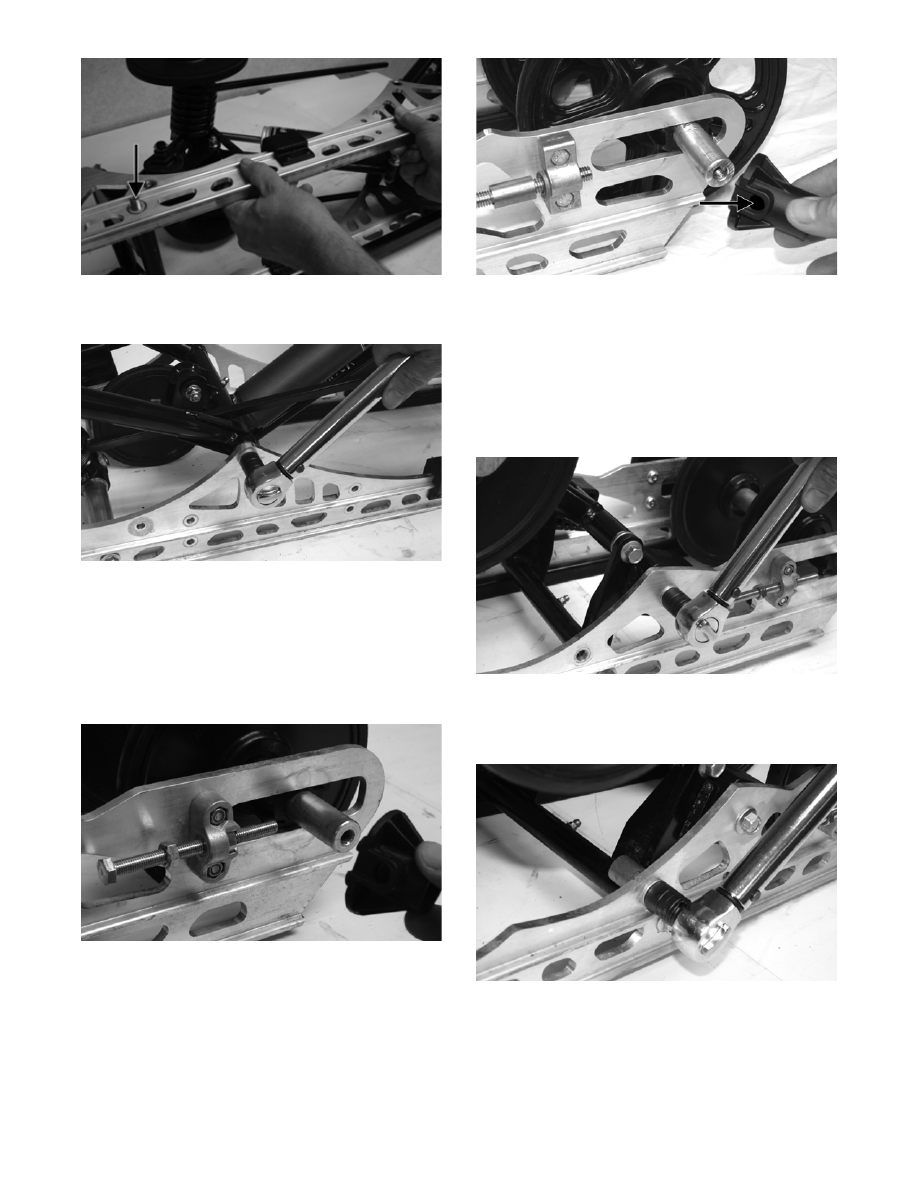
FZ084A
5. Secure the front arm to the slide rail with the cap
screws and lock nuts. Tighten to 32 ft-lb.
FZ070
NOTE: At this point, return to steps 3 and 4 and
tighten the rear arm and front arm cap screws and
lock nuts to 40 ft-lb.
6. Install the adjuster bushing and rear idler wheel.
Install a cap screw and flat washer. Tighten only
until snug.
FZ066
NOTE: Care must be taken that the adjuster
bushing slot with the hole is aligned properly with
the adjuster bolt.
CM261A
NOTE: It is advisable to tighten the rear idler
wheel axle only until snug until the skid frame has
been installed and track tension has been
adjusted; then the axle assembly must be tight-
ened to 20 ft-lb.
7. Install coupler block w/bushing. Secure with cap
screw. Tighten securely.
FZ076
8. Install the rear arm limiter and secure with the cap
screw. Tighten the cap screw (coated with blue
Loctite #243) to 50 ft-lb.
FZ075
9. Place the spring into the slide block; then place the
spring slide and slide block assembly into position
on the slide rail. Secure with a cap screw and
washer. Tighten to 20 ft-lb.