Snowmobile Arctic Cat (2008 year). Manual - part 135


  Index      Snowmobiles / ATV     Snowmobile Arctic Cat - service manual 2008 year


Search            


Content   ..  133  134  135  136   ..


Snowmobile Arctic Cat (2008 year). Manual - part 135


7-100

1. Clean the bearing with a clean cloth.

2. Inspect each idler wheel for cracks or damage.

3. Rotate the idler wheel bearing (by hand) and

inspect for binding or roughness.

4. If a bearing must be replaced, use this procedure.

A. Remove the bearing snap ring.

B. Using a suitable press or suitable driving tool,

remove the bearing from the inside of the

wheel.

C. Press the new bearing (on its outer race) into

the idler wheel.

MS006A

D. Install the snap ring making sure the “sharp

side” is directed away from the bearing.

MS007A

INSTALLING SLIDE RAIL IDLER 
WHEELS

1. Secure the mounting block on the slide rail with a

cap screw and lock nut. Tighten to 20 ft-lb.

„NOTE: For proper alignment, it is advisable to
install an idler wheel cap screw into the top mount-
ing block hole prior to tightening.

FZ031A

2. Place the idler wheel to the mounting block; then

secure the idler wheel assembly with a cap screw,

flat washer, and a lock nut. Tighten to 20 ft-lb.

FZ032

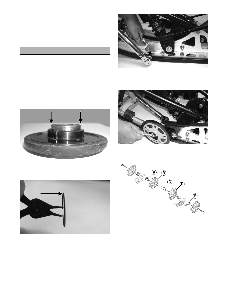
ASSEMBLING REAR AXLE

742-873A

1. In order from the right-hand side, slide the axle

through the slide rail axle slot; then place a bush-

ing (A), inner idler wheel (B), rear idler wheel

spacer (C), inner idler wheel (D), and bushing (E)

on the axle. Slide the axle through the opposite

slide rail axle slot.

2. Place the plastic adjuster bushings on the axle (on

the outside of each axle slot); then install the outer

idler wheels on the axle and secure with two cap

screws (coated with blue Loctite #243) and large

flat washers. Tighten cap screws only until snug.

! CAUTION

Do not remove the bearing unless it is absolutely
necessary. The bearing will be damaged during
removal.

7-101

7

ZJ266

FC194

„NOTE: It is advisable to tighten the rear idler
wheel axle only until snug until the skid frame has
been installed and track tension has been
adjusted; then the axle assembly must be tight-
ened to 20 ft-lb.

3. Install the skid frame (see Installing Skid Frame in

this sub-section).

4. Adjust track alignment (see Track Alignment in

this sub-section).

5. Adjust track tension deflection (see Track Tension

in this sub-section).

Front Arm Assembly

„NOTE: The skid frame must be removed for this
procedure (see Removing Skid Frame in this sub-
section), and the rear springs must be removed
from the adjusting cams.

REMOVING

1. Remove the cap screws and lock nuts securing the

limiter straps to the front arm. Account for flat

washers.

ZJ270A

2. Remove the cap screw and lock nut securing the

upper front shock absorber eyelet to the front arm.

Pull the shock eyelet free of the bracket. Account

for a sleeve.

ZJ271A

3. Remove the lock nut and cap screw securing the

rear shock pivot to the front arm.

FZ049A

4. Remove the cap screw and lock nut securing the

front arm to the front arm mounting bracket.

7-102

FZ050A

5. Remove the front arm and account for the front

arm axle.

6. Remove the cap screw securing the front outer

idler wheel to the idler wheel mounting block.

Account for lock nut, cap screw, and flat washer.

FZ029A

7. Remove the cap screw and lock nut securing the

idler wheel mounting block to the slide rail.

„NOTE: For ease of removal, remove the front
outer idler wheel and mounting block from the side
of the slide rail in which the front arm shock axle
cap screw was installed.

8. Remove the cap screws, washer, and lock nut from

the front shock axle; then from one side, tap the

assembly forward far enough for the axle assem-

bly to clear the slide rails. Account for an axle, two

spacers, and two shim washers.

FZ051A

FZ052

INSPECTING

„NOTE: Whenever a part is worn excessively,
cracked, or damaged in any way, replacement is
necessary.

1. Inspect all front arm weldments for cracks or

unusual bends; then inspect the front arm mount-

ing brackets for cracks and for elongated holes.

2. Closely inspect all tubing for cracks or unusual

bends.

3. Inspect the bearings, bushings, and front arm spac-

ers for wear or damage.

4. Inspect the shock absorber for damage and for any

signs of oil leakage especially at the point where

the shock shaft enters the shock body.

5. Inspect the shock absorber eyelet welds (at each

end) for any cracks, signs of separation, or for

unthreading.

INSTALLING

1. With the rubber bushing in place, install the axle

into the lower shock eyelet bushing assembly; then

install the two shim washers and two spacers.

CM246A

2. Place the front arm shock axle assembly into posi-

tion on the skid frame making sure the spacers and

washers are properly positioned. Secure with the

cap screw, washer, and a new lock nut. Tighten to

32 ft-lb.

7-103

7

FZ053

3. On the side that the idler wheel and mounting

block were removed from, secure the mounting

block on the slide rail with a cap screw and lock

nut. Tighten to 20 ft-lb.

„NOTE: For proper alignment, it is advisable to
install an idler wheel cap screw and lock nut into
the top mounting block hole prior to tightening.

FZ055A

4. Secure the idler wheel to the mounting block with a

cap screw and a lock nut. Tighten cap screw to 16

ft-lb.

FZ056

5. Install the axle into the front arm; then position the

front arm to the mounting location of the slide rail.

Secure with cap screws and lock nuts. Tighten to

32 ft-lb.

„NOTE: Move the rear arm assembly forward
enough to allow the rear arm springs to be
installed into the slide blocks.

FZ054

6. Secure the rear shock pivot to the front arm with

cap screw and lock nut. Tighten to 20 ft-lb.

FZ049

7. Secure the upper shock eyelet and axle in the

mounting hole of the front arm. Secure with a cap

screw and lock nut. Tighten securely.

ZJ271A

„NOTE: Do not over-tighten the shock absorber
cap screw as the shock eyelet must be free to
pivot.

8. Secure the limiter straps to the front arm with cap

screws, washers, and lock nuts. Tighten to 10 ft-lb.


Content   ..  133  134  135  136   ..