Snowmobile Arctic Cat (2008 year). Manual - part 133
7-92
CLEANING AND INSPECTING
NOTE: Whenever a part is worn excessively,
cracked, or damaged in any way, replacement is
necessary.
1. Clean the slide rail using parts-cleaning solvent
and compressed air.
2. Inspect the slide rail for cracks. If any cracks are
found, replace the slide rail.
3. Using a straightedge, inspect the slide rail for any
unusual bends. With the slide rail removed, place
the straightedge along the bottom surface of the
slide rail. If the rail is found to be bent, it must be
replaced.
AG536D
INSTALLING
NOTE: Apply a light coat of grease to the slide
rail surface to aid in installing a new wear strip. If
there are any sharp edges on the lower portion of
the rail, use a file to remove them.
1. Align the wear strip with the openings (windows)
in the track and from the back, start the wear strip
onto the rail; then using a block of wood and a ham-
mer, drive the wear strip forward into position.
739-884A
2. Secure with a machine screw and lock nut. Tighten
to 50 in.-lb.
End Caps
NOTE: The skid frame does not have to be
removed for this procedure.
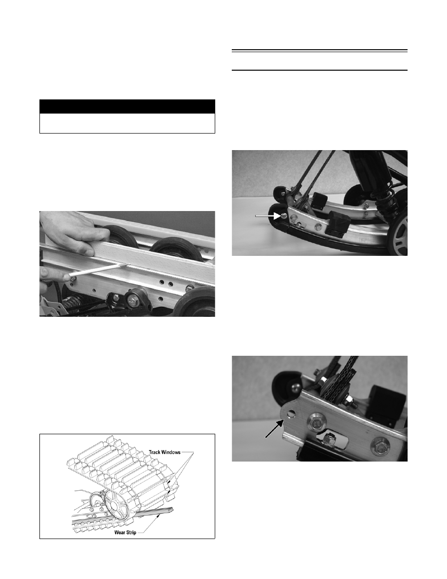
REMOVING
1. Remove the lock nut and cap screw securing the
end cap.
FZ026A
2. Using a hammer, tap the end cap off the rail.
CLEANING AND INSPECTING
NOTE: Whenever a part is worn excessively,
cracked, or damaged in any way, replacement is
necessary.
1. Inspect the end cap area of the slide rail for cracks
and wear.
FZ027A
2. Inspect the end cap for any signs of cracking or
wear.
! WARNING
Always wear an approved pair of safety glasses
when using compressed air.