Snowmobile Arctic Cat (2008 year). Manual - part 114
7-16
MS210A
MS210B
2. Place the idler wheel and axle assembly into posi-
tion between the slide rails. Tighten to 50 ft-lb.
MS211
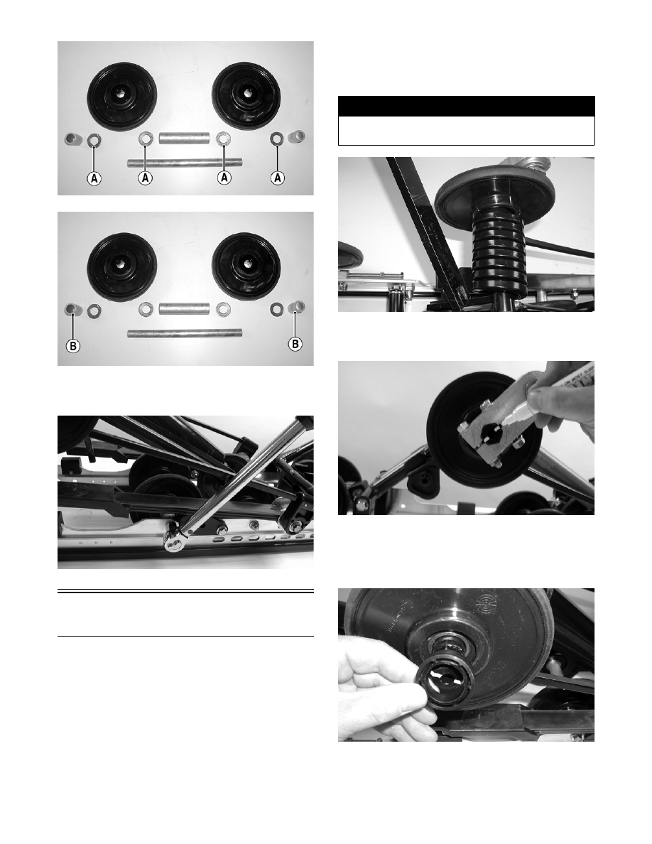
Rear Upper Idler
Wheels/Rear Springs
NOTE: The skid frame must be removed for this
procedure (see Removing Skid Frame in this sub-
section).
REMOVING
1. Using the Rear Suspension Spring Tool, remove
the spring from the adjusting cam.
MS063
2. Mark the pivot arm and the idler arm for assembly
purposes.
MS142
3. Remove the cap screws securing the pivot arm to
the idler arm; then remove the pivot arm assembly.
Account for a flanged axle, washer, flared bush-
ings, idler spacer collar, and lock nuts.
MS064
4. Using Idler Wheel Puller Kit, remove the wheel.
! WARNING
Care must be taken when removing the spring or
damage or injury could result.