Snowmobile Arctic Cat (2008 year). Manual - part 87
5
5-29
Troubleshooting
Electric Start
Ignition Timing
NOTE: Ignition timing can be checked and/or ver-
ified on all snowmobile engines.
CHECKING (All Models)
1. Connect a timing light to the MAG-side spark plug
lead.
2. Using a shielded safety stand, raise the rear of the
snowmobile off the floor and start the engine.
Gradually increase the engine speed to the speci-
fied RPM; the pointer should align with the proper
timing mark on the flywheel.
3. On the 370 cc if timing is not correct, adjust the
ignition timing.
ADJUSTING (370 cc)
1. Remove the recoil starter, starter pulley, and fly-
wheel.
2. Loosen the two screws securing the stator plate
and rotate the stator plate in the proper direction to
attain correct timing.
NOTE: Rotate the stator plate clockwise to retard
the timing or counterclockwise to advance the tim-
ing. The stamped marks on the stator plate at the
upper socket-head cap screw mounting hole can
be used for timing.
3. Tighten the screws securing the stator plate.
4. Install the flywheel, starter pulley, and recoil
starter.
5. Recheck timing for accuracy and adjust if neces-
sary.
Brakelight Switch
BEARCAT 570/PANTHER 370
Testing/Removing
1. Disconnect the wiring harness from the brake con-
trol.
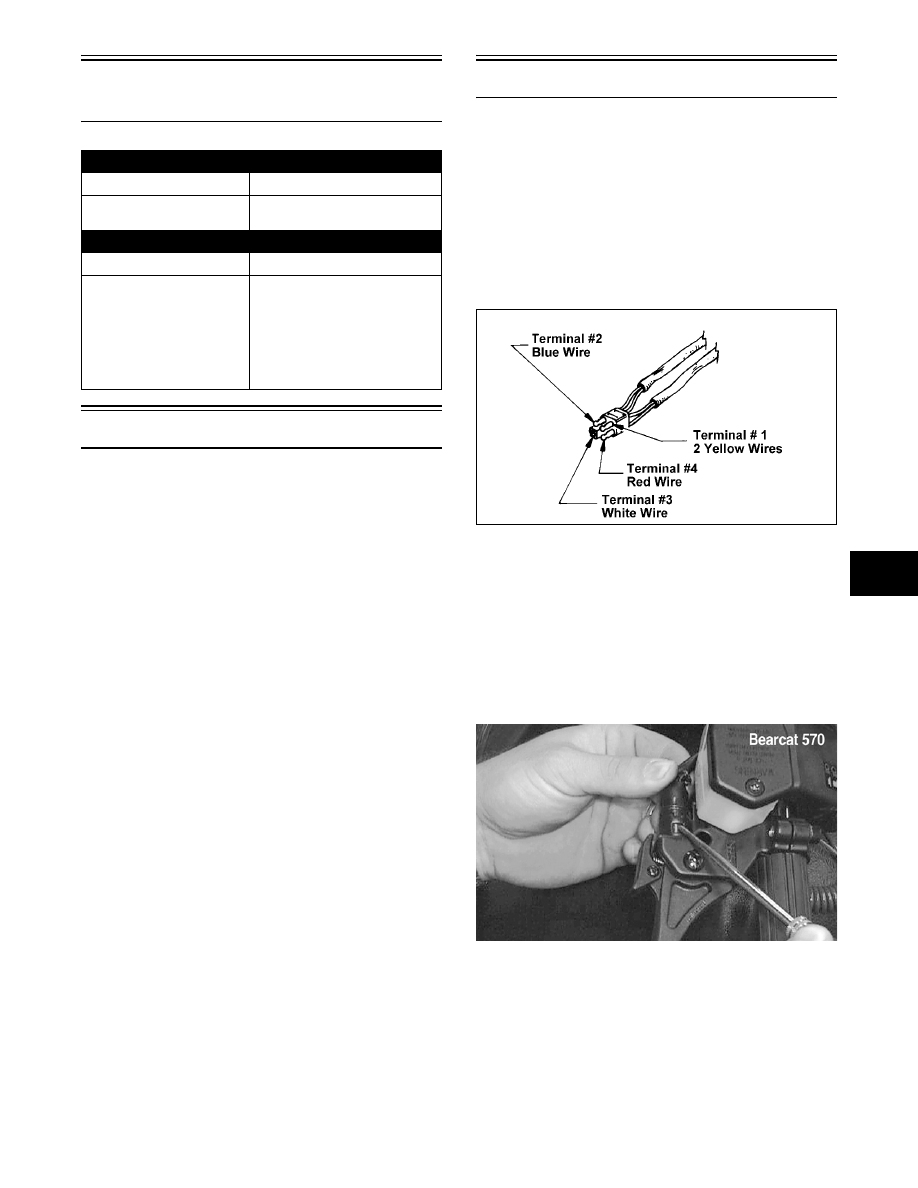
2. To test the brakelight switch, connect one tester
lead to the #1 (yellow) terminal; then connect the
other lead to the #4 (red) terminal.
727-650A
3. With the brake lever compressed, the meter must
read resistance. With the brake lever released, the
meter must read no resistance. If the meter does
not read as specified, the brakelight switch is
defective and must be replaced.
4. To remove the switch, use a small screwdriver to
compress the plastic locking tabs by pushing in on
the tabs; then slide the switch free of the brake
control.
AF201D
Problem: Hot or Smoking Wires
Condition
Remedy
1. System wired incor-
rectly
1. Check wiring against wir-
ing diagram
Problem: Starter Does Not Turn Over
Condition
Remedy
1. Battery discharged
2. Connection loose
3. Grounding improper
4. Fuse blown - not
installed
1. Check/charge the battery
2. Check tightness of all
connections
3. Check round connections
4. Check - replace fuse