Snowmobile Arctic Cat (2008 year). Manual - part 79
4-32
NOTE: Before starting the engine, make sure
that no air is present in the testing equipment.
8. With the control arm secured in the FULL-OPEN
position (line-to-line), run the engine at recom-
mended RPM for 2 minutes. Compare the amount
of oil used against the specifications on the chart
in Section 1.
9. If the oil-injection pump output does not meet the
specifications, see Testing Oil-Injection Check
Valves in this sub-section.
10. Disconnect the oil usage tool, remove the plug
from the reservoir, attach the oil-supply hose to the
oil reservoir, and remove the vacuum pump.
NOTE: After testing the oil pump, it is critical
that the oil pump is correctly synchronized with
the carburetor(s)/throttle bodies (see Synchroniz-
ing Oil-Injection Pump on page 30 in this section).
Testing Oil-Injection
Check Valves
In the event there is an engine problem due to lack of
lubrication, the oil-injection pump check valves should
be tested using a vacuum pump to make sure the check
valves are operating properly.
When testing the check valves, remove them from the
pump assembly.
1. Remove the check valves from the oil-injection
pump.
731-551A
2. Attach the vacuum test pump hose to the check
valve.
3. Squeeze the vacuum pump handle and watch the
pump gauge. The check valve should release at
4.5-5 lb and again reset itself at 3.5-4 lb. If
“release” and “reset” are not within specifications,
replace the check valve.
4. Record the “release” and “reset” readings for the
valve; then perform the test on the other valve.
The “release” and “reset” readings must fall within
specifications and must be within 1.5 lb of each
other. If either or both are not met, replace the
check valves.
5. If the check valves are within specifications but
the oil-injection usage is not, replace the oil-injec-
tion pump.
Fuel Pump
(Carbureted Models)
PRELIMINARY CHECKS
1. Make sure the gas tank shut-off valve is in the
OPEN position.
2. Make sure there is adequate gasoline in the gas
tank.
3. Make sure all hoses are clear and free of kinks and
obstructions.
4. Make sure the fuel filter is not plugged or dam-
aged.
5. Make sure fuel and impulse hoses are in good con-
dition.
6. Make sure there is evidence of good impulse at the
crankcase impulse fitting.
TESTING PRESSURE
1. Connect a pressure gauge between fuel pump and
carburetor using a piece of fuel hose and a T-fit-
ting.
2. Place snowmobile on a safety stand and start the
engine. At the following engine speeds, the speci-
fied pressures must be indicated.
3. Remove gauge and hose and connect fuel hose to
carburetor.
! CAUTION
Whenever servicing the oil-injection system, use a
100:1 gas/oil mixture in the gas tank to ensure ade-
quate engine lubrication. Failure to use the 100:1
mixture to the oil-injection system will result in
severe engine damage.
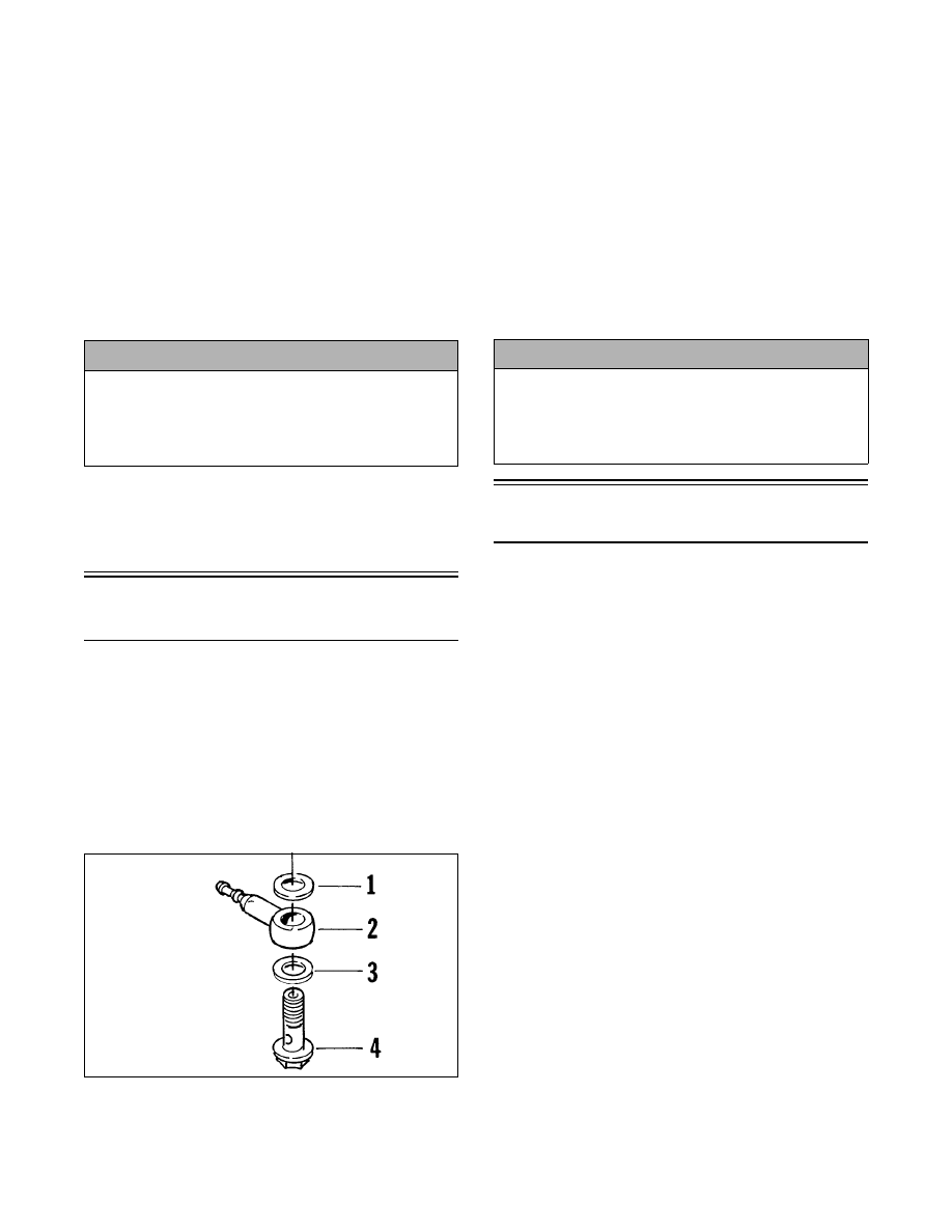
KEY
1. Gasket
2. Check Valve
3. Gasket
4. Union
! CAUTION
Whenever servicing the oil-injection system, use a
100:1 gas/oil mixture in the gas tank to ensure ade-
quate engine lubrication. Failure to use the 100:1
mixture to the oil-injection system will result in
severe engine damage.