Snowmobile Arctic Cat (2008 year). Manual - part 77
4-24
EFI Analyzer/
Diagnostic Tool
NOTE: For testing the 800/1000 cc EFI system,
refer to the EFI Diagnostic System Manual, which
accompanies Laptop Diagnostic Tool and Laptop
Diagnostic Test Kit.
NOTE: To aid in testing the 500/600 cc EFI sys-
tem, refer to the EFI Analyzer Usage Manual, which
accompanies EFI Analyzer Kit.
Throttle Body
Assembly
741-871A
0740-804
0741-330
REMOVING
NOTE: The expansion chamber and air silencer
must be removed for this procedure (see Section
2).
1. Disconnect the wiring harness from each injector
and from the throttle position sensor connector.
2. Remove the coolant hoses from the throttle body
assembly and plug them to prevent leakage.
3. Remove the fuel supply hose from the fuel rail.
4. Loosen the flange clamps.
5. Slide the throttle body assembly out of the flanges;
then loosen the jam nut securing the throttle cable
and remove.
6. Where applicable, remove the oil pump control
rod.
7. Remove the throttle body assembly.
INSTALLING
1. Attach the throttle cable to the throttle body.
Secure with jam nut.
2. Place the throttle body assembly into position.
Make sure the flanges and boots are positioned
properly. Secure with flange clamps.
3. Where applicable, connect the oil pump control
rod.
KEY
1. Throttle Body
2. Throttle Position
Sensor
3. Screw
4. O-Ring
5. Fuel Rail
6. Bolt
7. Fuel Injector
8. Cushion
500 cc
600 cc
KEY
1. Throttle
Body
2. Fuel Rail
3. Fuel Injector
4. Screw
5. Hose
6. Clamp
7. O-Ring Set
8. Throttle Position Sensor
9. Screw
10. Control Rod
! CAUTION
Since the fuel supply hose may be under pressure,
remove it slowly to release the pressure. Place an
absorbent towel around the connection to absorb
fuel.
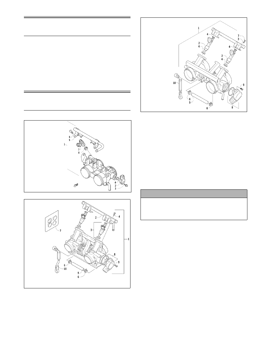
KEY
1. Throttle Body
2. Fuel Injector
3. Fuel Rail
4. O-Ring
5. Hose
6. Clip
7. Screw
8. Throttle Position
Sensor
9. Screw
10. Control Rod
800/1000 cc