Snowmobile Arctic Cat (2008 year). Manual - part 72
4-4
Removing Carburetor
NOTE: On twin carburetor models, remove the
carburetors using this basic procedure.
1. Turn the gas tank shut-off valve to the CLOSED
position.
2. Remove the mixing body top by rotating it coun-
terclockwise; then remove the top with spring,
plate, jet needle with E-clip, and piston valve from
the carburetor.
CM047
3. Remove the brass choke-cable housing from the
carburetor. Account for a washer.
CM048
4. Disconnect the fuel hose from the carburetor inlet
fitting.
AH284D
5. If applicable, disconnect the safety switch wiring
harness connector from the main wiring harness.
6. Loosen the carburetor-flange clamp; then remove
the carburetor.
CM049
NOTE: Slide the carburetor into the air-intake
silencer boot until free of the flange; then remove
carburetor.
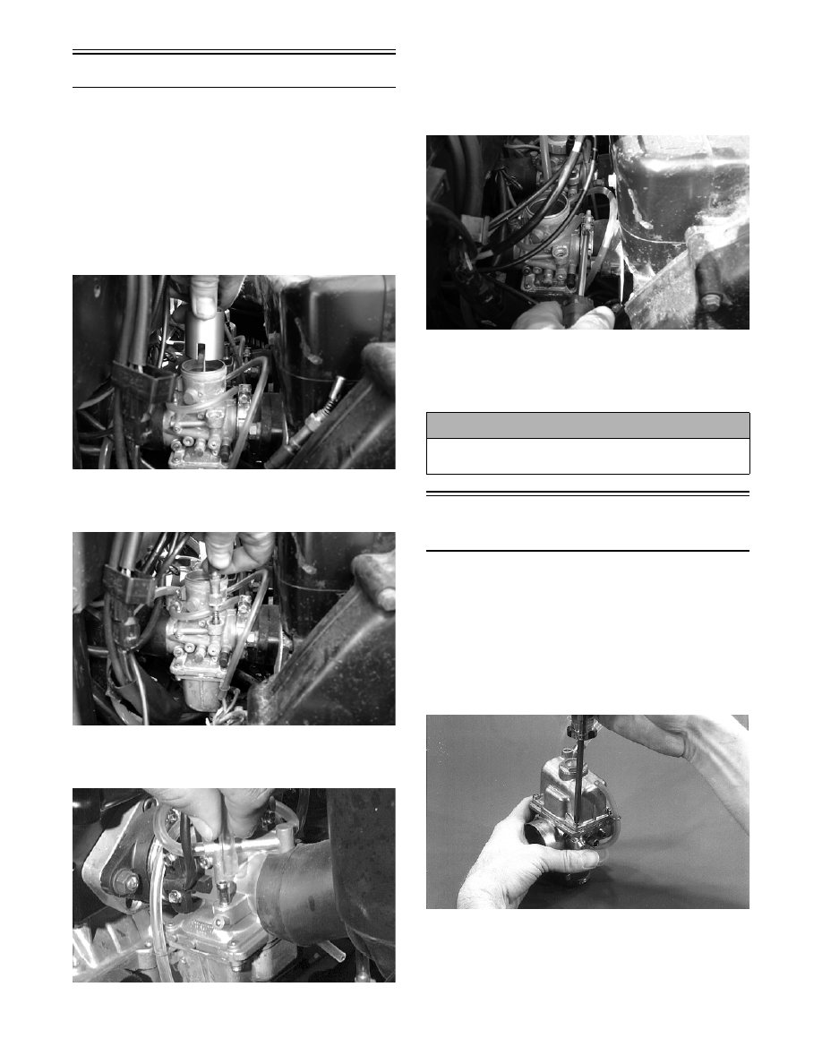
Disassembling
Carburetor
NOTE: On twin carburetor models unless there
is a problem with the safety switches, do not
loosen or remove the screws securing the switch
to the carburetor.
1. Remove the four screws and lock washers secur-
ing the float chamber; then remove the float cham-
ber and gasket.
AH144
NOTE: The floats should be removed only if
replacement is necessary or the float chamber
requires cleaning with carburetor cleaner.
! CAUTION
Keep MAG-side and PTO-side carburetors identified
for installing purposes.