Snowmobile Arctic Cat (2008 year). Manual - part 70


  Index      Snowmobiles / ATV     Snowmobile Arctic Cat - service manual 2008 year


Search            


Content   ..  68  69  70  71   ..


Snowmobile Arctic Cat (2008 year). Manual - part 70


3-24

Check for correct exhaust valve cable length specifica-

tions for model being worked on in this section.

Servomotor Makes No Attempt To 
Cycle

If when running the engine the servomotor makes no

attempt to operate, this is caused by one or more of the

following:

A. Bad connection from the wiring harness and

connector from the lighting coil to the CCU, to

the ECU, or from the ECU to servomotor.

B. CCU output (gauge/taillight/APV) is shorted or

open.

C. ECU output to servomotor is too low.

D. Servomotor failure.

„NOTE: For testing individual APV system compo-
nents, see Section 5.

MAINTENANCE

The APV system requires only periodic cleaning and

cable adjustment. The cables should be checked every

1000-2000 miles and adjusted as necessary. To ensure

maximum performance and minimize maintenance

requirements, Arctic Cat recommends using Arctic Cat

Synthetic APV 2-Cycle Oil. Using oils other than the

recommended oil may increase the frequency of

required cleaning due to increased buildup of carbon

deposits.

CABLE ADJUSTMENT

Proper cable adjustment is critical to the operation of

the APV system. While it is recommended that the

cable adjustment be inspected every 1000-2000 miles,

the cable should not need adjustment often. To check

the cable adjustment, use the following procedure.

1. On the Crossfire/M-Series, remove the two cap

screws securing the servomotor cover.

FC004

2. Using a small needle-nose pliers, remove the ser-

vomotor retaining clip (800/1000 cc) and the cable

holder.

FS273A

CM127

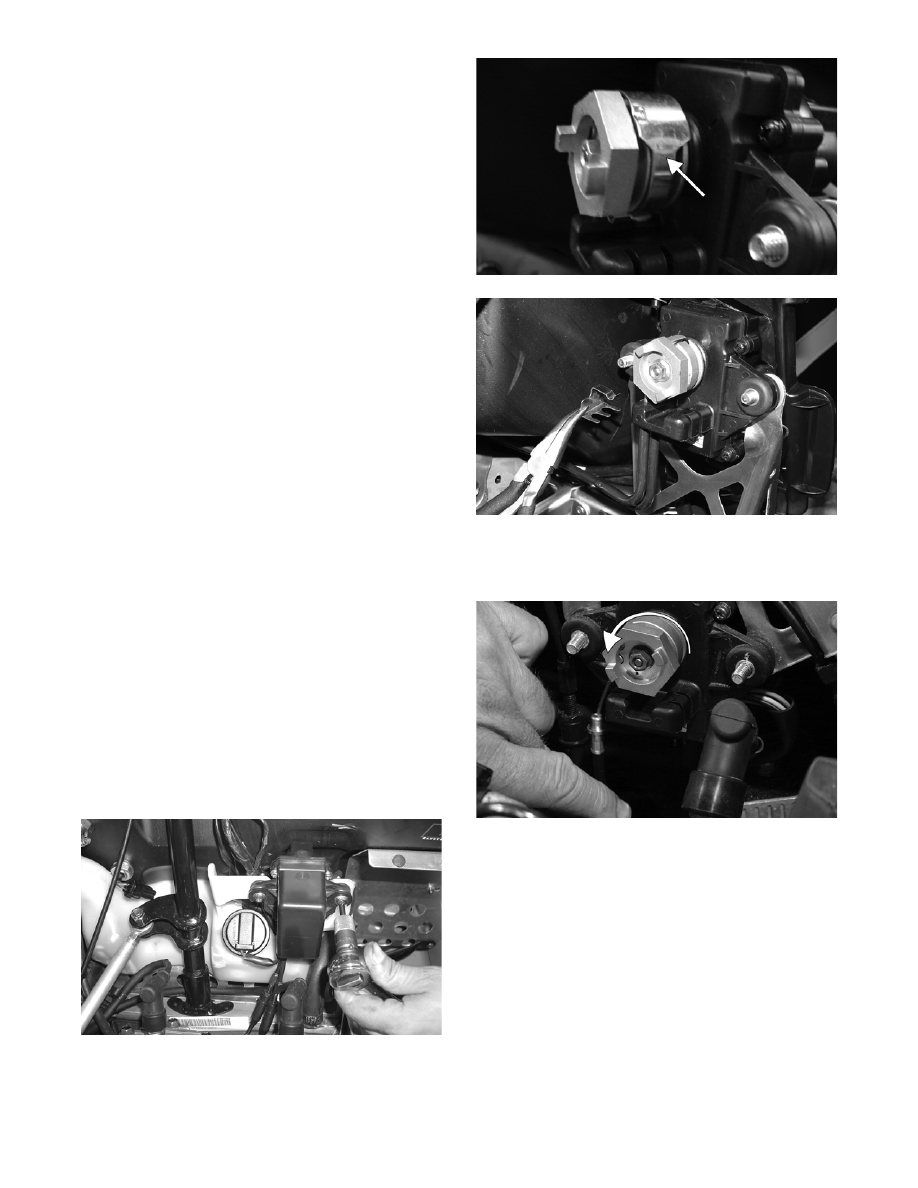
3. Rotate the servomotor actuator counterclockwise

to loosen the cable; then pull the cable housings

down and out of the servomotor.

CM123A

„NOTE: For installing purposes, note the side that
the servomotor cables are installed on.

4. Slide each cable drum out of the slot of the servo-

motor actuator.

3-25

3

CM124A

„NOTE: Before proceeding with the cable adjust-
ment, ensure that the exhaust valves are free to
move.

5. While holding the cable housing firmly, pull the

cable as far out as it will go; then release. Repeat

three to four times. The cable/exhaust valve

should move freely without binding. If the cable/

exhaust valve does not move freely, the exhaust

valve assembly will need to be removed for further

inspection.

„NOTE: When measuring the cables, they are to
be routed and as close to their installed position
as possible.

6. While holding the cable housing, lightly pull on

one cable end to remove any slack.

7. Measure the amount of exposed cable from the

cable housing to the end of the cable.

„NOTE: The two cable measurements must be
equal in length or less than 0.5 mm (0.020 in.) dif-
ference in length from each other.

„NOTE: Repeat steps 6 and 7 for each cable; then
compare the measurements to the appropriate
chart in Section 1.

„NOTE: The measurements must be within the
specifications from the chart. If the measurements
are within specifications, no adjustment is neces-
sary. If they are not within specifications, proceed
to step 8.

8. Loosen the jam nut on the cable to be adjusted;

then using the adjusting nuts, lengthen or shorten

the housing as needed.

9. Once the proper length has been attained, hold the

adjusting nut in place and tighten the jam nut

securely.

10. Place the cable housings into position in the servo-

motor. Secure the cable housings with the cable

holder and retaining clip (800/1000 cc).

11. On the Crossfire/M-Series, place the servomotor

cover into position; then secure with two cap

screws.

„NOTE: If for any reason the pulley was removed
from the servo, make certain to align the space
between the two cable slots with the mark on the
shaft of the servo. Tighten the nut to 35 in.-lb.

MS401A

FZ087A

REMOVING/DISASSEMBLING

„NOTE: To avoid a parts mix-up, it is recom-
mended that only one valve assembly at a time be
removed from the engine.

1. Remove the exhaust valve assembly from the

engine.

! CAUTION

Never attempt to remove or install the servo pulley
jam nut with the pulley unsecured or damage to the
servomotor will occur.

3-26

FC115

CM147

2. Remove the retaining screw securing the exhaust

valve to the valve stopper.

FC112

3. Hold the valve stopper securely and pull the cable

back and up until it clears the top of the stopper;

then slowly release the cable and remove it from

the valve stopper.

FC113

Cleaning and Inspecting

1. Remove all carbon deposits with solvent and a soft

abrasive such as a Scotch-Brite pad.

2. Inspect all parts for nicks, burrs, or other signs of

unusual wear.

Replacing Oil Seal

1. Carefully pry the seal up from beneath taking care

not to damage the valve plate.

FC116

2. Install the new seal using an appropriate-sized seal

driving tool.

FC117

600 cc

800/1000 cc

3-27

3

ASSEMBLING/INSTALLING

FC111A

1. Slide the return spring over the end of the actuat-

ing cable.

FC114

„NOTE: Make sure that the small cable end spring
stays in place at the end of the cable.

2. With the cover gasket properly positioned, place

the valve stopper on the cable end and slide it

down until the cable end is inside the stopper.

FC113

3. With the valve plate gasket properly positioned,

slide the exhaust valve through the valve plate and

insert it into the valve stopper. Secure with the

retaining screw. Tighten to 48 in.-lb.

FC112

„NOTE: Note that the exhaust valve gaskets are
directional and must be installed correctly.

4. Slide the exhaust valve assembly into the cylinder.

FC115

CM147

KEY

A. Exhaust Valve

B. Cover Gasket

C. Valve Plate

D. Oil Seal

E. Gasket

F. Stopper

G. Stopper Pin

H. Return Spring

I. Valve Cover

! CAUTION

On the 600 cc, the long side of the exhaust valve
must be facing toward the cylinder head or severe
engine damage may occur.

600 cc

800/1000 cc


Content   ..  68  69  70  71   ..