Snowmobile Arctic Cat (2008 year). Manual - part 49


  Index      Snowmobiles / ATV     Snowmobile Arctic Cat - service manual 2008 year


Search            


Content   ..  47  48  49  50   ..


Snowmobile Arctic Cat (2008 year). Manual - part 49


2-134

FC014

FC015

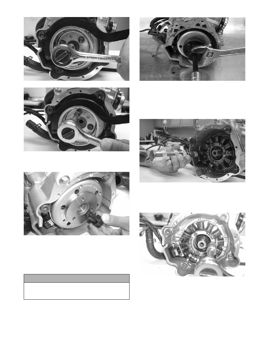
2. Install Flywheel Pulley Insert onto the end of the

crankshaft.

FC016

3. Using Flywheel Puller or suitable substitute,

remove the flywheel from the crankshaft by tight-

ening the puller bolt, striking the head of the puller

bolt with a hammer, and tightening again. Repeat

this procedure until the flywheel is free. Account

for the key.

CM013

„NOTE: To ensure the cleanliness of the flywheel
magnets, place the flywheel (with the magnets fac-
ing upward) on a clean bench.

4. Remove the ignition timing sensor.

FC022

5. Remove the Allen-head cap screws securing the

stator to the stator plate. Move the stator to the

side to access the Phillips-head cap screw securing

the stator lead wire; then remove the cap screw.

FC018

6. On the 600 cc, remove the Allen-head cap screws

securing the magneto case to the crankcase.

Account for four alignment pins.

„NOTE: Note the different-sized cap screws for
assembling purposes.

! CAUTION

To prevent damage to the crankshaft, do not thread
puller bolts more than 12.7 mm (1/2 in.) into the fly-
wheel. Damage to the coils may result.

2-135

2

FC019

FC020

7. Remove the stator plate from the engine.

FC021

FC065

„NOTE: The stator plate screws had Loctite
applied to the threads during assembly. Using an
impact driver, apply a sharp blow to the head of
each screw to break the Loctite loose before
removal.

8. On the 600 cc, remove the cap screws securing the

APV assemblies to the cylinders; then remove the

APV assemblies and set them aside.

„NOTE: Note that the APV exhaust valves and
gaskets are directional for assembling purposes.

FC023

FC024

FC025

9. Remove the spark plugs.

10. Remove the cap screws with O-rings securing the

cylinder head; then separate from the cylinders.

Account for the O-rings.

11. Remove the oil-injection hose from each flange.

2-136

FC026

„NOTE: When removing the cylinders, place the
engine on its intake flanges on a drain tray to allow
residual coolant to drain from the cylinder/crank-
case water jacket.

12. On the 500 cc, remove the eight nuts securing the

cylinders to the crankcase; then using a rubber

hammer, gently tap the cylinders and remove from

the crankcase by lifting them straight up off their

studs. Account for gasket(s) and any alignment

pins.

13. On the 600 cc, remove the four nuts and four bolts

securing the cylinders to the crankcase; then using

a rubber hammer, gently tap the cylinders and

remove from the crankcase by lifting them straight

up off their studs. Account for gasket(s) and any

alignment pins.

FC067

FC027

14. Remove the PTO-side piston-pin circlip from the

PTO-side piston; then remove the MAG-side pis-

ton-pin circlip from the MAG-side piston.

CM149

15. Using Piston Pin Puller, remove the piston pins

from both pistons.

„NOTE: For proper assembly, keep all MAG-side
components and all PTO-side components sepa-
rated. Assemble them on their proper sides.

FC029

16. Lift the pistons clear of the connecting rods and

remove the small-end connecting-rod bearings

(account for two washers); then remove the piston

rings. Keep each piston with its rings; keep each

piston pin and bearing together as a set.

! CAUTION

When removing a cylinder, be sure to support the
piston to prevent damage to the crankcase and pis-
ton.

! CAUTION

DO NOT use any type of punch to drive the piston
pin free of the piston; damage may result. Use a pis-
ton-pin puller only.

2-137

2

AN317D

„NOTE: On the 500 cc, place rubber bands over
the connecting rods and around the cylinder
studs. This will prevent the connecting rods from
damaging the crankcase. On the 600 cc, use rub-
ber hoses to secure the connecting rods.

17. Remove the intake flanges and reed valve assem-

blies.

FC030

18. Remove the three cap screws securing the thermo-

stat cap; then remove the cap, gasket, and thermo-

stat.

FC032

19. Remove the six screws securing the water pump

cover to the crankcase and remove the cover.

Account for the O-ring gasket and the alignment

pins.

20. Remove the cap screw securing the water pump

impeller; then slide the impeller free of the shaft.

21. Remove either lower union cap screw securing the

lower check valve assembly; then remove the two

screws securing the oil-injection pump to the

crankcase. Remove the pump, retainer, and O-ring.

FC031

22. Turn the engine upside down on support blocks

and remove the water temperature sensor switch.

FC033

23. With its bottom side up on two support blocks,

remove the cap screws securing the crankcase

halves.

24. Separate the crankcase halves by installing two

crankcase cap screws in opposite corners leaving

the heads approximately 6 mm (1/4 in.) out. Using

a plastic hammer and lifting on the ends of the

crankshaft, tap on each cap screw head until the

case halves separate. Remove the cap screws.

! CAUTION

DO NOT drive any tool between halves to separate
the crankcase. Damage to the sealing surfaces will
result.


Content   ..  47  48  49  50   ..