Snowmobile Arctic Cat (2008 year). Manual - part 47


  Index      Snowmobiles / ATV     Snowmobile Arctic Cat - service manual 2008 year


Search            


Content   ..  45  46  47  48   ..


Snowmobile Arctic Cat (2008 year). Manual - part 47


2-125

2

14. Place the throttle bodies into position and secure

with the flange clamps. Verify oil-injection pump

synchronization (see Section 4); then connect the

fuel line to the throttle body assembly and tighten

the clamp securely.

FC051

15. Install the oil pump linkage arm to the throttle

body pulley.

CM129B

16. Connect the two coolant hoses to the throttle body

assembly; then secure with the clamps.

CM131A

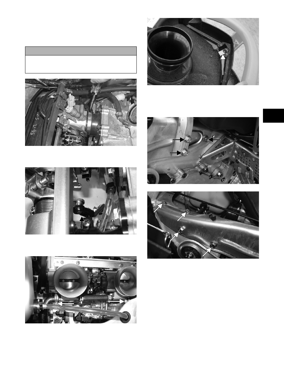
17. With the air silencer boot properly positioned on

the throttle body assembly, install the silencer and

secure with the hold-down and the torx-head cap

screw.

CM026A

18. Install the side-plate brace onto the chassis and

secure the brace and the steering support with the

cap screws (coated with blue Loctite #243).

Tighten securely.

CM132A

CM133A

„NOTE: It is advisable to install the two front lower
cap screws first to attain proper alignment for the
remaining cap screws.

! CAUTION

When installing the throttle bodies, make sure the
gasline hose is properly routed to avoid premature
wear and/or contact with exhaust components.

2-126

CM133B

19. Apply a thin coat of high-temperature silicone

sealant to each exhaust port; then install the

exhaust gaskets.

20. Slide the APV cable drums into the servomotor

actuator; then place the cable housings into posi-

tion in the servomotor. Secure the cable housings

with the cable holder.

CM127

21. Rotate the servomotor clockwise to remove any

slack from the cables; then install the servomotor

retaining clip.

CM185

22. Place the servomotor cover into position; then

secure with two lock nuts.

CM121A

23. Check APV cable adjustment. See Arctic Power

Valve (APV) System in Section 3.

„NOTE: Before installing the drive clutch, be sure
to wipe both the crankshaft taper and clutch
mounting taper clean using a clean towel.

24. Place the drive clutch into position on the crank-

shaft and secure with the cap screw and lock

washer. Tighten to 55 ft-lb.

„NOTE: On the 1000 cc to aid in proper tightening
of the drive clutch cap screw, apply oil to the
threads of the cap screw prior to installing.

25. Install the alignment washers (if applicable); then

install the driven pulley on the gear case input

shaft. Tighten the cap screw to 32 ft-lb.

CM125A

26. Check drive clutch/driven pulley alignment (see

Section 6).

! CAUTION

When installing the drive clutch, do not tighten the
clutch cap screw with any kind of impact tool.
Tighten cap screw using a hand torque wrench only.
Failure to do so could result in stationary sheave
damage.

2-127

2

MS390

27. Install the drive belt. Check belt deflection. Secure

the belt guard (see Section 6).

28. Install the resonator and secure with the hairpin

clip and springs; then place the expansion chamber

and grafoil gaskets into position and secure to the

exhaust manifold and resonator with the springs.

„NOTE: When installing the four exhaust manifold
springs, the long hook portion of the spring must
be attached to the exhaust manifold or premature
spring failure will result.

29. Fill the cooling system (see Liquid Cooling Sys-

tem in Section 3).

30. Place the hood into position on the front end and

secure with the two pins and the cables.

31. Connect the ignition harness to the ECU and the

hood harness to the main harness; then connect the

air intake connector.

CM038

32. Start the engine and warm up to operating temper-

ature; then verify that all components are function-

ing properly and that coolant is circulating through

the cooling system properly.

33. Allow the engine to cool; then check the coolant

level and add coolant as necessary. Verify the

tightening torque of the drive clutch.

! CAUTION

After running the engine to the proper operating tem-
perature, shut the engine off; then open the hood
and access panels and inspect for any signs of cool-
ant, gasoline, or oil leakage.

! CAUTION

Never run the engine with the hood harness discon-
nected or damage to the electrical system will result.

! CAUTION

If the engine had a major overhaul or if any major
component was replaced, proper engine break-in
procedures must be followed (see Section 1). If the
proper engine break-in procedures are not followed,
severe engine damage may result.

2-129

2

Engine - 

F-Series 500/600 - 

T-Series 500

This engine servicing sub-section has been organized

to show a progression for the complete servicing of the

Arctic Cat 500 cc/600 cc (F-Series/T-Series) engines.

For consistency purposes, this sub-section shows a

complete and thorough progression; however, for effi-

ciency it may be preferable to remove the engine as a

complete assembly, to remove and disassemble only

those components which need to be addressed, and to

service only those components. Also, some compo-

nents may vary from model to model. The technician

should use discretion and sound judgment.

„NOTE: Critical torque specifications can be
found in Section 1 of this manual.

„NOTE: Some illustrations and photographs used
in this section are used for clarity purposes only
and are not designed to depict actual conditions.

SPECIAL TOOLS

A number of special tools must be available to the

technician when performing service procedures in this

engine section.

„NOTE: Special tools are available from the Arctic
Cat Service Parts Department.

Table of Contents

Removing ............................................................ 2-129
Disassembling ..................................................... 2-133
Cleaning and Inspecting...................................... 2-138
Measuring Critical Components .......................... 2-141
Assembling.......................................................... 2-144
Installing .............................................................. 2-151

Removing Engine

1. Remove the hood and the left-side and right-side

access panels; then remove the torx-head screws

securing the console.

741-722A

2. Lift the rear of the console and disconnect the con-

sole/main harness plug-in; then remove the con-

sole.

3. Remove the hairpin clip and all springs securing

the expansion chamber and resonator; then remove

these components from the engine compartment.

Account for the two exhaust gaskets.

„NOTE: On the LXR, disconnect the negative
cable from the battery.

4. On the standard models, push down on both seat

retainer brackets (located in the rear storage com-

partment) and remove the seat.

„NOTE: On the LXR and Sno Pro models with the
seat adjusted to its lowest position, remove the
self-tapping screw from the right-side seat adjust-
ment track; then remove the seat.

Description

p/n

Ball Hone

0644-292

Drive Clutch Puller

0644-207

Drive Clutch Spanner Wrench

0644-136

Driven Pulley Puller

0644-468

Flywheel Puller

0744-040

Flywheel Pulley Insert

0644-179

Oil Seal Protector Tool

0644-219

Piston Pin Puller

0644-328

Surface Plate

0644-016

Water Pump Bearing and Seal Kit

0644-502

V Blocks

0644-022


Content   ..  45  46  47  48   ..