Snowmobile Arctic Cat (2008 year). Manual - part 44


  Index      Snowmobiles / ATV     Snowmobile Arctic Cat - service manual 2008 year


Search            


Content   ..  42  43  44  45   ..


Snowmobile Arctic Cat (2008 year). Manual - part 44


2-113

2

„NOTE:  Make sure the smaller reading is 1.5 mm
(0.059 in.) or less for the 800 cc or 1.49 mm (0.058
in.) or less for the 1000 cc.
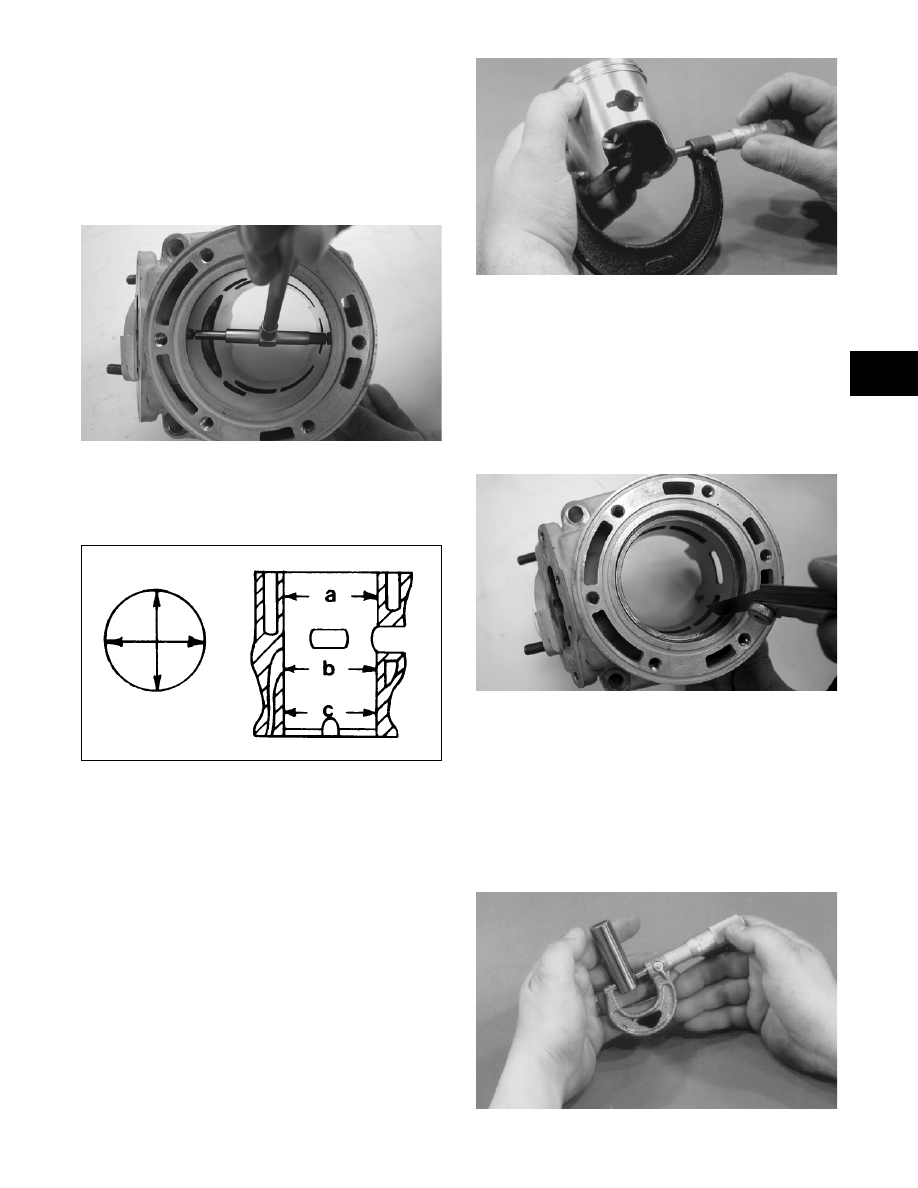
CYLINDER TRUENESS

1. Measure each cylinder in the three locations from

front to back and side to side for a total of six read-

ings.

FC044

2. The trueness (out-of-roundness) is the difference

between the highest and lowest reading. Maxi-

mum trueness (out-of-roundness) must not exceed

0.1 mm (0.004 in.).

0725-586

PISTON SKIRT/CYLINDER 

CLEARANCE

1. Measure each cylinder front to back about 2.5 cm

(1 in.) from the bottom of each cylinder.

2. Measure the corresponding piston skirt diameter at

a point 1 cm above the piston skirt at a right angle

to the piston-pin bore. Subtract this measurement

from the measurement in step 1. The difference

(clearance) must be within 0.075-0.0105 mm

(0.0029-0.0041 in.).

AC091

PISTON-RING END GAP

1. Place each piston ring in the wear portion above the

exhaust port of its respective cylinder. Use the pis-

ton to position each ring squarely in each cylinder.

2. Using a feeler gauge, measure each piston-ring

end gap. Acceptable ring end gap must be within

0.30-0.50 mm (0.012-0.0196 in.).

FC045

PISTON PIN AND PISTON-PIN BORE

1. Measure the piston pin diameter at each end and in

the center. Acceptable piston pin measurement

must be within 21.995-22.000 mm (0.8659-0.8661

in.) for the 800 cc or 23.995-24.000 mm (0.9447-

0.9449 in.) for the 1000 cc. If any measurement

varies by more than 0.02 mm (0.001 in.), the pis-

ton pin and bearing must be replaced as a set.

AN056

2-114

2. Insert a snap gauge into each piston-pin bore; then

remove the gauge and measure it with a micrometer.

The diameter measurement must be within 22.002-

22.010 mm (0.8662-0.8665 in.) for the 800 cc or

24.002-24.010 mm (0.9450-0.9453 in.) for the 1000

cc. Take two measurements to ensure accuracy.

AC092

CONNECTING-ROD SMALL END 
BORE

1. Insert a snap gauge into each connecting-rod small

end bore; then remove the gauge and measure it

with a micrometer.

AN061

2. The diameter measurement must be within

27.003-27.011 mm (1.0631-1.0634 in.) for the 800

cc or 29.003-29.011 mm (1.1410-1.1420 in.) for

the 1000 cc.

CRANKSHAFT RUNOUT

0742-727

1. Using the V Blocks, support the crankshaft on the

surface plate.

„NOTE: The V blocks should support the crank-
shaft on the outer bearings.

2. Mount a dial indicator and base on the surface

plate. Position the indicator contact point against

the crankshaft location point A (PTO-end) from

the crankshaft end. Zero the indicator and rotate

the crankshaft slowly. Note the amount of crank-

shaft runout (total indicator reading).

„NOTE: For runout location point specifications,
see Crankshaft Runout Specifications in Section 1
of this manual.

3. Position the indicator contact point against the

crankshaft location point B (MAG-end) from the

crankshaft end. Zero the indicator and rotate the

crankshaft slowly. Note the amount of crankshaft

runout (total indicator reading).

FC046

4. Position the indicator contact point against the

crankshaft at location point C (center). Zero the

indicator and rotate the crankshaft slowly. Note

the amount of crankshaft runout (total indicator

reading).

5. If runout exceeds 0.05 mm (0.002 in.) at any of the

checkpoints, the crankshaft must be either

straightened or replaced.

Assembling Engine

„NOTE: The use of new gaskets and seals is rec-
ommended when assembling the engine.

„NOTE: Before the engine is assembled, clean the
threads of the cap screws and the threaded areas
of the engine where loctite will be used.

„NOTE: When the use of a lubricant is indicated,
use Arctic Cat Synthetic APV 2-Cycle Oil.

1. Apply a thin coat of grease to the inner seal lips of

the water pump seal.

2-115

2

2. Using the seal driver, position the inner water

pump shaft seal onto the seal driver and gently tap

the seal down into position.

„NOTE: Grease must be applied to the lips of the
inner seal before installation.

MS986A

„NOTE: The seal must be installed with its spring
side towards the crankshaft.

3. Install the snap ring securing the inner seal in the

crankcase.

MS415

4. Using the seal driver, carefully install the outer

water pump seal. Gently tap the seal down into

position until it seats itself against its flange.

MS988

5. Apply a thin coat of grease to the sealing surface

of the oil-injection pump/water pump driveshaft;

then place the Oil Seal Protector Tool at the end of

the shaft. Twist the driveshaft clockwise as it is

pushed through the oil and water pump seals; then

remove the tool. 

FS191

6. Position the shim on the oil-injection pump end of

the driveshaft.

CM159A

7. Secure the upper crankcase half upside-down on a

suitable support; then install the C-ring (A), the

four bearing retaining pins (B), and the two crank-

case dowel pins (C).

! CAUTION

Be very careful not to damage the seals when
installing the oil pump driveshaft. Be certain to use
the seal protector tool. Twist the driveshaft clock-
wise as it enters the seal area and while it is being
pushed through the seals.

2-116

CM165C

8. Place the crankshaft end bearings into position

making sure the bearing retaining pin hole is posi-

tioned inward.

„NOTE: The bearing retaining pin hole is the hole
that does not go entirely through the bearing case.

CM043A

9. Lubricate the inner lips of the crankshaft oil seals

with grease; then slide the seals onto the crank-

shaft making sure the spring side of each seal faces

inward.

„NOTE: There is a MAG-side seal and a PTO-side
seal.

10. Apply oil to the crankshaft bearings; then install

the crankshaft into the upper crankcase half. Be

sure the alignment hole in each bearing is posi-

tioned over its respective dowel pin in the crank-

case; then seat the crankshaft.

CM045A

„NOTE: To check the bearing for proper position,
place the point of a sharp tool into the dimple
found in the bearing race. Strike the tool with the
palm of the hand in either direction. If the bearing
moves, it isn’t positioned correctly and must be
rotated until it drops onto the dowel pin.

11. Position the two center seal rings with their end

gaps 180° apart (up on one and down on the

other); then apply a thin coat of High-Temp Seal-

ant to the entire bottom half of the crankcase seal-

ing surface.

CM036A

CM166

„NOTE: Use only Arctic Cat High-Temp Sealant to
seal the crankcase halves.

12. Assemble the crankcase halves making sure that

the crankshaft gear and oil-injection pump drive-

shaft gears mesh. Rotate the crankshaft one full

turn to align the crankshaft gear and pump drive-

shaft.

13. Install the crankcase cap screws securing the

crankcase halves. 

14. Tighten cap screws (1-10) in three steps to 31 ft-lb

using the appropriate pattern shown.

! CAUTION

If the bearings are not properly seated during
assembly, the crankcase halves will not seal tightly
and severe engine damage will result.


Content   ..  42  43  44  45   ..