Snowmobile Arctic Cat (2008 year). Manual - part 42


  Index      Snowmobiles / ATV     Snowmobile Arctic Cat - service manual 2008 year


Search            


Content   ..  40  41  42  43   ..


Snowmobile Arctic Cat (2008 year). Manual - part 42


2-105

2

CM191A

„NOTE: On the 1000 cc, remove the coolant
bypass hoses from the cylinders.

8. Remove the cap screws and nuts securing the cyl-

inders to the crankcase; then using a soft hammer,

gently tap the cylinders and remove from the

crankcase by lifting them straight up off their

studs. Account for gasket(s) and alignment pins.

CM192

„NOTE: If servicing the MAG-side only, the PTO-
side cylinder must be removed.

„NOTE: After the cylinders have been removed, it
is advisable to cover the crankcase to avoid com-
ponents falling into the crankcase.

9. Remove the PTO-side piston-pin circlip from the

PTO-side piston; then remove the PTO-side pis-

ton-pin circlip from the MAG-side piston.

10. Using Piston Pin Puller and Medium Extractor

Nut, remove the piston pins from both pistons.

CM193

„NOTE: The piston pins must be removed from the
PTO-side of the piston.

„NOTE: For proper assembly, keep all MAG-side
components and all PTO-side components sepa-
rated. Assemble them on their proper sides.

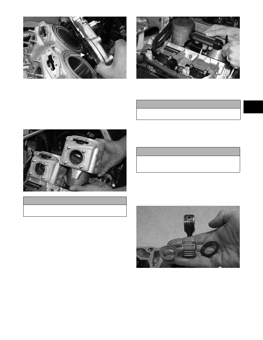
11. Lift the pistons clear of the connecting rods and

remove the small-end connecting-rod bearings

(account for two washers); then remove the piston

rings. Keep each piston with its rings; keep each

piston pin and bearing together as a set.

CM151

„NOTE: Place a suitable length of rubber hose
around the connecting rods. This will prevent the
connecting rods from damaging the crankcase.

„NOTE: For servicing procedures, see Cleaning
and Inspecting Engine and Measuring Critical
Components in this sub-section.

! CAUTION

When removing a cylinder, be sure to support the pis-
ton to prevent damage to the crankcase and piston.

! CAUTION

Do not use the large extractor nut to remove the pin
or damage to the piston may occur.

! CAUTION

DO NOT use any type of punch to drive the piston
pin free of the piston; damage may result. Use a pis-
ton-pin puller only.

2-106

INSTALLING TOP-SIDE 
COMPONENTS

1. Place the cylinder base gasket and alignment pins

into position on the crankcase.

2. Install the piston rings on each piston so the letter

on the top (inclined surface) of each ring faces the

dome of the piston.

726-306A

3. Apply oil to the connecting-rod small end bear-

ings; then install the small-end bearings. Install a

washer on each side of the connecting rod.

„NOTE: The shoulder side of the washer must
seat to the needle bearing.

CM172A

„NOTE: Prior to installing the pistons, make sure
to install the MAG-side piston pin circlips first.

4. Place each piston over the connecting rod so the

indicator dot on each piston will point toward the

intake/exhaust ports; then secure with an oiled pis-

ton pin.

„NOTE: The indicator dot (A) is found on the pis-
ton dome.

CM194A

5. Install the new circlips so the open end is directed

either up or down.

CM195B

6. Rotate each piston ring until the ring ends are

properly positioned on either side of the ring

keeper; then apply oil to the piston assemblies and

cylinder bores. Remove the rubber hoses from the

connecting rods.

7. In turn on each cylinder, place a piston holder (or

suitable substitute) beneath the piston skirt and

square the piston in respect to the crankcase; then

using a ring compressor or the fingers, compress

the rings and slide the cylinder over the piston.

Remove the piston holder and seat the cylinder

firmly onto the crankcase.

! CAUTION

Incorrect installation of the piston rings will result in
engine damage.

! CAUTION

Make sure the circlips are firmly seated and the open
end is directed either up or down before continuing
with assembly.

! CAUTION

The cylinders should slide on easily. DO NOT force
the pistons into the cylinders.

2-107

2

CM192

8. Secure each cylinder by installing the four nuts

and four cap screws. DO NOT TIGHTEN AT

THIS TIME.

„NOTE: Never reuse cylinder cap screws. Always
replace with new cap screws.

„NOTE: The cylinders will be tightened after the
exhaust manifold is installed to assure proper cyl-
inder to exhaust manifold alignment.

9. Apply a thin coat of high-temperature silicone

sealant to each exhaust port; then install the

exhaust gaskets.

CM196

10. Apply a thin coat of high-temperature silicone

sealant to the mating surfaces of the exhaust mani-

fold; then install the exhaust manifold and secure

with eight nuts. Tighten the nuts using the pattern

shown to 17 ft-lb.

0742-292

11. Secure the cylinders (from step 8) by tightening

the cylinder base nuts and cap screws to 42 ft-lb in

three steps using the appropriate pattern shown.

0738-206

0738-220

12. Install the hose clamp onto the cylinder head cool-

ant hose with the clamp screw directed outward

(toward the PTO-side of the engine).

CM199A

13. Install the coolant hose and secure the hose onto

the cylinder head; then install the coolant bypass

hose onto the head.

„NOTE: On the 1000 cc, install the coolant bypass
hoses onto the cylinders.

„NOTE: After the coolant hose has been secured
to the cylinder head, secure the cylinder head up
and out of the way of the cylinder to allow the cyl-
inder O-rings to be installed.

800 cc

1000 cc

2-108

CM191

14. Lubricate the O-rings with a light coat of grease;

then install the two cylinder O-rings on the top of

each cylinder making sure they are correctly posi-

tioned in the grooves.

FC077

„NOTE: Lubricating the O-rings with a light coat of
grease will help keep them seated in the grooves
of the cylinder.

15. Place new O-rings onto each of the head cap

screws. Place four of these cap screws (from oppo-

site end of each other) into the cylinder head.

Thread the spark plugs in part way; then while

holding the head above the cylinder, carefully start

all four cap screws while observing the cylinder

O-rings to make sure they remain in position.

Slowly place the head into position on top of the

O-rings. 

CM175

„NOTE: On the 800 cc to install the remaining cap
screws, the spark plugs must be removed.

16. Start the remaining cap screws being very careful

not to move the cylinder head. ONLY FINGER-

TIGHTEN AT THIS TIME; then tighten the cap

screws in two steps to 25 ft-lb using the appropri-

ate pattern shown.

0742-200

0742-199

17. On the 800 cc, install the spark plugs and on both

models, tighten the spark plugs to 19 ft-lb; then

install the spark plug wires.

„NOTE: On the 800 cc, connect the knock sensor
plug-in.

18. Install the APV gaskets into position as noted dur-

ing disassembly; then with the raised edge (A) of

the bottom of the valve aligned with the channel (B)

of the cylinder, install the APV’s onto the cylinder

and secure with the cap screws. Tighten to 10 ft-lb.

CM147A

19. Install the side-plate brace; then secure with the

cap screws (coated with blue Loctite # 243).

800 cc

1000 cc


Content   ..  40  41  42  43   ..