Snowmobile Arctic Cat (2008 year). Manual - part 40


  Index      Snowmobiles / ATV     Snowmobile Arctic Cat - service manual 2008 year


Search            


Content   ..  38  39  40  41   ..


Snowmobile Arctic Cat (2008 year). Manual - part 40


2-97

2

CM137

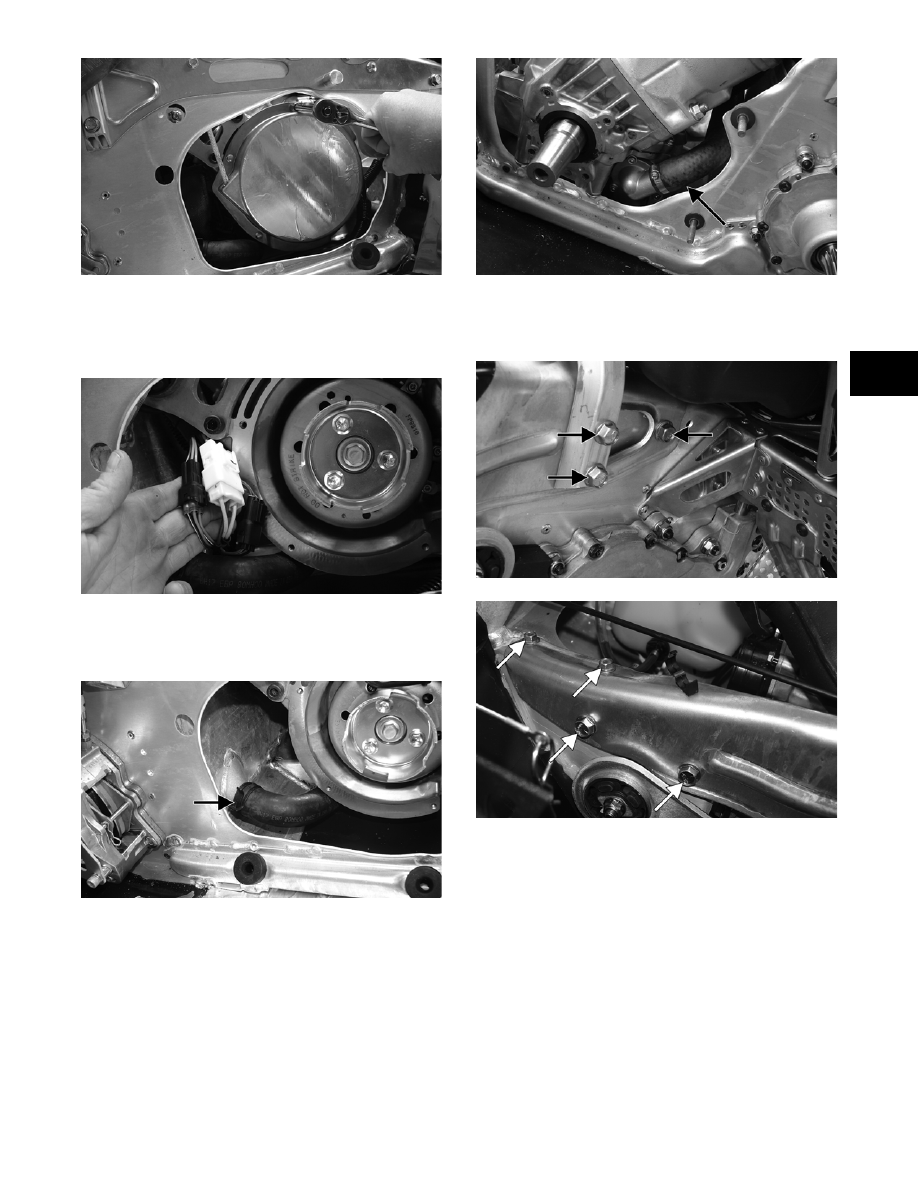
18. Remove the wiring harness wrap; then disconnect

the ignition/main harness connectors and the tem-

perature sensor connector. Secure the harness out

of the way.

CM134

19. Disconnect the lower coolant hose from the front

heat exchanger; then remove the remaining cool-

ant hose from the thermostat outlet.

CM135A

CM136A

20. Remove the cap screws and lock nuts securing the

steering support and the side-plate brace to the

chassis.

CM132A

CM133A

21. Remove the lock nuts (A) and (B) from the cap

screws of the MAG-side engine mounting bracket

and the front lower engine mounting bracket (do

not remove the cap screws at this time).

2-98

742-203B

22. Remove the lock nuts (C) securing the PTO-side

engine mounting bracket to the chassis.

23. Remove the cap screws (D) securing the PTO-side

engine mounting bracket to the engine.

24. Remove the PTO-side engine mounting bracket; then

remove the cap screws (A) and (B) from step 21.

25. Lift the engine out of the engine compartment.

26. Remove the exhaust manifold and engine mount-

ing brackets from the engine. Account for nuts and

gaskets.

27. Remove the clamp securing the coolant supply

hose from the cylinder head to the water pump.

Then remove the hose from the engine.

CM181

Disassembling Engine

„NOTE: When disassembling top-side compo-
nents, mark MAG-side and PTO-side components
for assembling purposes.

1. Using the spanner wrench to secure the flywheel,

remove the flywheel cap screw and washer; then

remove the three starter pulley cap screws and

remove the pulley.

CM138

CM139

2. Install Flywheel Pulley Insert onto the end of the

crankshaft.

FC016

3. Using Flywheel Puller or suitable substitute,

remove the flywheel from the crankshaft by tight-

ening the puller bolt, striking the head of the puller

bolt with a hammer, and tightening again. Repeat

this procedure until the flywheel is free. Account

for the key.

! CAUTION

To prevent damage to the crankshaft, do not thread
puller bolts more than 1/2 in. into the flywheel. Dam-
age to the coils may result.

2-99

2

CM140

„NOTE: To ensure the cleanliness of the flywheel
magnets, place the flywheel (with the magnets fac-
ing upward) on a clean bench.

„NOTE: On the 1000 cc, remove the Allen-head
cap screws securing the magneto case to the
crankcase. Account for the alignment pins.

CM144A

4. Remove the cap screw securing the ground wire to

the crankcase.

CM142A

5. Remove the Allen-head cap screw (A) securing

the stator lead wire plate to the crankcase; then

remove the Allen-head cap screws (B) securing

the timing sensors, remove the sensors, and

account for the harness grommets.

CM141C

6. Remove the Allen-head cap screws securing the

stator to the stator plate. Route the stator lead wire

out of the crankcase; then remove the stator

assembly.

CM143A

7. Remove the cap screws securing the stator plate to

the engine; then remove the plate.

CM145D

„NOTE: For assembling purposes, note that the
indentation (A) of the stator plate is aligned with
the harness opening (B) in the crankcase.

2-100

CM145C

„NOTE: The stator plate screws had Loctite
applied to the threads during assembly. Using an
impact driver, apply a sharp blow to the head of
each screw to break the Loctite loose before
removal.

8. Remove the cap screws securing the APV assem-

blies to the cylinders; then remove the APV

assemblies and set them aside.

„NOTE: For assembling purposes, note that the
APV exhaust valves and gaskets are directional.

CM146A

CM147

9. Remove the spark plugs.

„NOTE: On the 800 cc at this point, remove the
knock sensor and lock plate from the cylinder
head by bending the lock plate tabs down and
unthreading the sensor.

10. Remove the cap screws with O-rings securing the

cylinder head; then separate from the cylinders.

Account for the O-rings.

„NOTE: When removing the cylinders, place the
engine on its intake flanges on a drain tray to allow
residual coolant to drain from the cylinder/crank-
case water jacket.

11. Remove the four nuts and four cap screws secur-

ing the cylinders to the crankcase; then using a soft

hammer, gently tap the cylinders and remove from

the crankcase by lifting them straight up off their

studs. Account for gasket(s) and alignment pins.

CM148

12. Remove the PTO-side piston-pin circlip from the

PTO-side piston; then remove the MAG-side pis-

ton-pin circlip from the MAG-side piston.

CM149

13. Using Piston Pin Puller, remove the piston pins

from both pistons.

„NOTE: For proper assembly, keep all MAG-side
components and all PTO-side components sepa-
rated. Assemble them on their proper sides.

! CAUTION

When removing a cylinder, be sure to support the
piston to prevent damage to the crankcase and pis-
ton.


Content   ..  38  39  40  41   ..