Snowmobile Arctic Cat (2008 year). Manual - part 25


  Index      Snowmobiles / ATV     Snowmobile Arctic Cat - service manual 2008 year


Search            


Content   ..  23  24  25  26   ..


Snowmobile Arctic Cat (2008 year). Manual - part 25


2-37

2

MD0269

MD0268

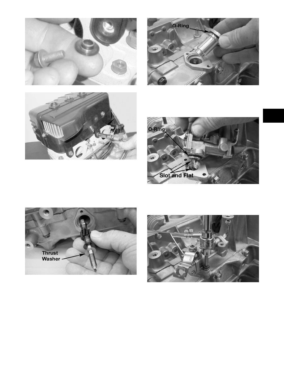
26. Lubricate the oil-injection pump driveshaft; then

while rotating the driveshaft, install it and the

thrust washer into the lower crankcase half.

„NOTE: Make sure the thrust washer is installed
on the oil injection pump driveshaft when it is
installed.

MD0252

27. With a new O-ring in place, install the oil injection

pump driveshaft retainer.

MD0273

28. With a new O-ring in place, install the oil injection

pump aligning the slot on the oil pump with the

flat on the end of the oil injection pump driveshaft.

Tighten the Allen-head cap screws to 8 ft-lb.

MD0294

„NOTE: For assembling purposes, always use
new O-rings lubricated with oil on the oil injection
pump and retainer.

MD0090

29. Install the first set of gaskets, heat deflector,

remaining gaskets, insulators, and flanges and

secure with nuts and washers. Tighten the nuts

(threads coated with red Loctite #271) to 15 ft-lb.

30. Install the exhaust manifold and gaskets with a

thin coat of High-Temp Sealant using lock wash-

ers and nuts. Tighten the nuts to 15 ft-lb.

2-38

Installing Engine

1. Place each engine mounting bracket onto the

engine. Secure with cap screws (coated with blue

Loctite #243), washers, and lock washers. Tighten

to 25 ft-lb.

2. Place the engine assembly into position in the

engine compartment. Secure the engine to the

front end with the cap screws, washers, and lock

nuts. Tighten to 25 ft-lb.

570-ENG07A

3. Connect the oil-supply hoses to the oil-injection

pump.

„NOTE: If equipped with electric start, place the
starter motor bracket on the crankcase and install
the front two and lower rear cap screws, lock wash-
ers, and washers. Place the starter motor into posi-
tion and secure with two washers and lock nuts.

4. Connect the oil-injection cable to the oil-injection

pump control arm and secure the cable mounting

pin with a nylon washer and E-clip.

5. Place the carburetors into position making sure the

boots are properly positioned and secure with the

flange clamps.

„NOTE: At this point, bleed the oil-injection sys-
tem and check synchronization (see Section 4).

6. Connect the impulse hose to the crankcase, the

main wiring harness, the CDI unit wiring harness,

and the spark plug caps.

„NOTE: If equipped with electric start, secure the
battery ground cable with the rear cap screw.

7. Place the expansion chamber and grafoil gasket

into position and secure with springs.

AB105D

8. Place the engine mount shims into position

between the torque bumper and engine mounting

bracket; then tighten the torque bumper jam nut.

9. Place the drive clutch into position on the crank-

shaft; then install the lock washer and bolt.

Tighten the clutch bolt to 55 ft-lb.

CM016

„NOTE: Before installing the drive clutch, be sure
to wipe both the crankshaft taper and clutch
mounting taper clean using a clean towel.

„NOTE: Apply a coat of Anti-Seize Thread Com-
pound to the keyway end of the driven shaft.

10. Install the driven pulley and alignment washers.

Secure with a cap screw (threads coated with blue

Loctite #243) and washer tightened to 24 ft-lb.

! CAUTION

When installing the carburetors, make sure the
gasline hoses are properly routed to avoid prema-
ture wear and/or contact with exhaust components.

! CAUTION

When installing the drive clutch, do not tighten the
clutch bolt with any kind of impact tool. Tighten bolt
using a hand torque wrench only. Failure to do so
could result in stationary sheave damage.

2-39

2

SC013D

„NOTE: At this point, check drive clutch/driven
pulley alignment (see Section 6).

11. Install the drive belt and secure the belt guard.

Install the plug in the belly pan.

„NOTE: If equipped with electric start, connect the
battery.

12. Check the ignition timing.

13. Place the rear of the snowmobile up on a shielded

safety stand. Start engine and allow to warm up.

Adjust engine idle to 1500 RPM and check all

safety switches for proper operation.

14. Test drive the snowmobile; then verify the tighten-

ing torque of the drive clutch.

Engine - F 570/T570

This engine servicing sub-section has been organized

to show a progression for the complete servicing of the

Arctic Cat 570 cc (F 570/T570) engine. For consis-

tency purposes, this sub-section shows a complete and

thorough progression; however, for efficiency it may

be preferable to remove the engine as a complete

assembly, to remove and disassemble only those com-

ponents which need to be addressed, and to service

only those components. Also, some components may

vary from model to model. The technician should use

discretion and sound judgment.

„NOTE: Critical torque specifications can be
found in Section 1 of this manual.

„NOTE: Some illustrations and photographs used
in this section are used for clarity purposes only
and are not designed to depict actual conditions.

SPECIAL TOOLS

A number of special tools must be available to the

technician when performing service procedures in this

engine section.

„NOTE: Special tools are available from the Arctic
Cat Service Parts Department.

Table of Contents

Removing .............................................................. 2-39
Disassembling ....................................................... 2-42
Cleaning and Inspecting........................................ 2-47
Measuring Critical Components ............................ 2-51
Assembling............................................................ 2-53
Installing ................................................................ 2-60

Removing Engine

1. Remove the hood and the left-side and right-side

access panels; then remove the torx-head screws

securing the console.

741-722A

2. Lift the rear of the console and disconnect the con-

sole/main harness plug-in; then remove the con-

sole and diconnect the battery.

! CAUTION

If the engine had a major overhaul or if any major
component was replaced, proper engine break-in
procedures must be followed (see Section 1). If the
proper engine break-in procedures are not followed,
severe engine damage may result.

Description

p/n

Ball Hone

0644-292

Crankshaft Bearing Remover

0144-302

Drive Clutch Puller

0644-207

Drive Clutch Spanner Wrench

0644-136

Driven Pulley Puller

0644-468

Flywheel Spanner Wrench

0144-007

Flywheel Puller

0744-040

Piston Pin Puller

0644-328

Surface Plate

0644-016

V Blocks

0644-022

2-40

3. Remove the springs securing the expansion cham-

ber to the exhaust manifold and resonator and

remove the expansion chamber; then remove the

cap screw, lock nut, and washer securing the reso-

nator to the front upper frame and remove the res-

onator.

4. Remove the cap screws and lock nuts securing the

heat shield to the chassis. Account for the U-nut clip.

FZ016A

5. Remove the cap screws securing the recoil starter.

Account for the ground wire.

FZ002

„NOTE: For assembling purposes, note the loca-
tion of the recoil cap screw securing the ground
wire.

6. Remove the cap screw and lock nut from the lower

rope retaining roller on the MAG-side engine

mount; then move the recoil starter up and out of

the way.

FZ020A

7. Remove the two pins securing the belt guard and

remove the drive belt; then using a 1/2-in. 12-point

socket, remove the cap screw and lock washer

securing the drive clutch to the crankshaft.

8. Using Drive Clutch Puller and an impact wrench

or a breaker bar and Spanner Wrench, tighten the

puller. If the drive clutch will not release, sharply

strike the head of the puller. Repeat this step until

the clutch releases. Remove the drive clutch and

the drive belt. If applicable, account for the two

sleeves.

9. Remove the cap screw from the driven pulley and

slide the driven pulley off the gear case input shaft.

Account for alignment washers (if applicable).

FZ021

„NOTE: If the driven pulley is tight on the driven
shaft, pull the driven pulley off using the Driven
Pulley Puller.

10. Remove the lock nuts and cap screw securing the

snubber bracket to the chassis; then remove the

bracket.

FZ007A

11. Remove the nuts and lock washers securing the

exhaust manifold to the engine; then remove the

manifold and account for the gaskets.


Content   ..  23  24  25  26   ..