Snowmobile Yamaha FX10X, FX10RTX, FX10RTRX, FX10RTRAX, FX10MTX, FX10MTRX, FX10MTRAX. Manual - part 32
4-17
POWR
TR
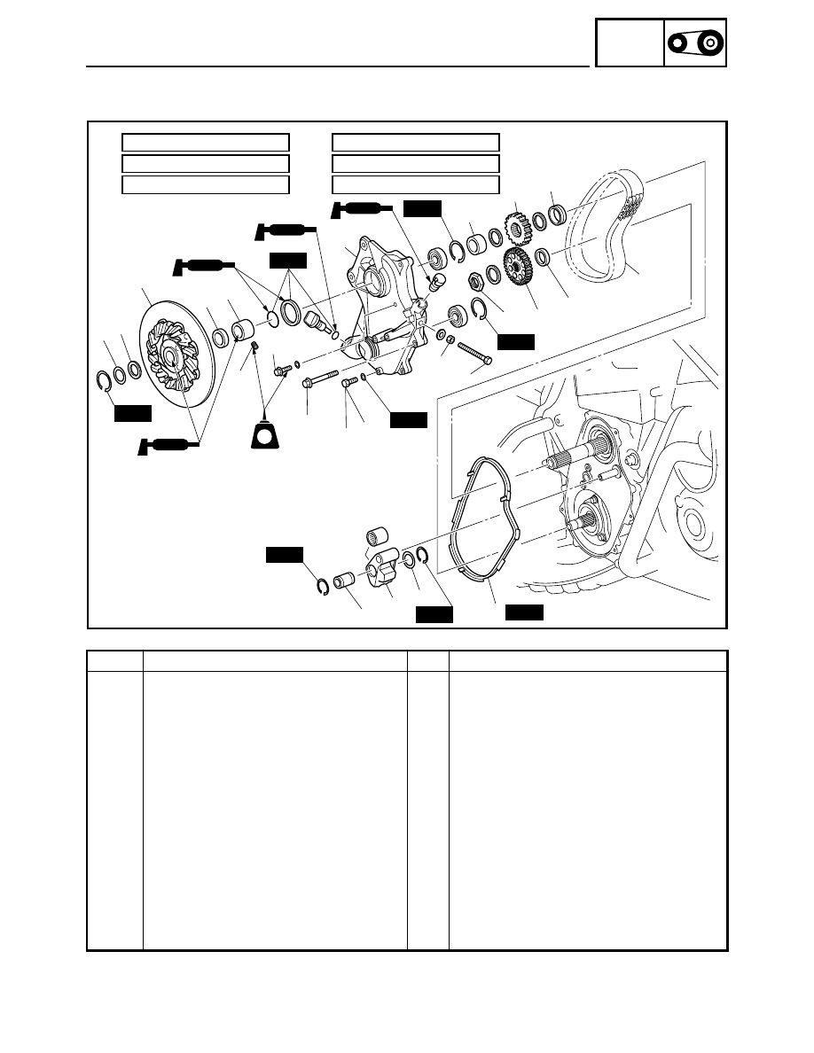
DRIVE CHAIN
WITHOUT REVERSE MODEL
Order
Job name/Part name
Q’ty
Remarks
Drive chain removal
Remove the parts in the order listed below.
Right lower cover
Refer to “COVERS” in CHAPTER 3.
Brake caliper/Parking brake
Refer to “BRAKE”.
1
Shim
—
t = 0.5
2
Washer
1
t = 1.0
3
Brake disc
1
4
Collar
1
5
Drain bolt
1
Drain.
6
Chain tension adjusting bolt
1
Loosen.
7
Collar
1
8
Drive chain cover
1
9
Rubber seal
1
10
Chain tensioner
1
11
Washer
1
t = 0.5
12
Collar
1
Ê
Ë
Í
É
È
Ì
New
New
New
New
New
New
New
New
1 2
3
7
5
(5)
4
6
8
15
16
LT
17
18
13
11
10
12
9
14
6 Nm (0.6 m
•
kg, 4.3 ft
•
lb)
È:
10 Nm (1.0 m
•
kg, 7.2 ft
•
lb)
É:
16 Nm (1.6 m
•
kg, 11 ft
•
lb)
Ê:
25 Nm (2.5 m
•
kg, 18 ft
•
lb)
Ë:
28 Nm (2.8 m
•
kg, 20 ft
•
lb)
Ì:
90 Nm (9.0 m
•
kg, 65 ft
•
lb)
Í: