Snowmobile Polaris High Performance (2001 year). Manual - part 58


  Index      Snowmobiles / ATV     Snowmobile Polaris High Performance - service manual 2001 year


Search            


Content   ..  56  57  58  59   ..


Snowmobile Polaris High Performance (2001 year). Manual - part 58


CHASSIS/BRAKES/FINAL DRIVE

5.8

Brake Bleeding - Fluid Change

Brake Bleeding - Fluid Change

This procedure should be used to change fluid or bleed brakes during regular maintenance, or after complete
brake service. Brake fluid may damage painted or plastic surfaces. Take care not to spill, and wipe up any spills
immediately. Cover parts to avoid damage.

1.

Clean reservoir cover thoroughly.

2.

Remove screws, cover, and diaphragm from
reservoir.

3.

Inspect vent slots (A) in cover and remove any
debris or blockage.

4.

If changing fluid, remove fluid from reservoir with a
Mity Vac

pump or similar tool.

NOTE: Do not remove brake lever when reservoir fluid
level is low.

5.

Add brake fluid to within 1/4-5/16

(.6-.8 cm) of

reservoir top.

6.

Install a box end wrench on caliper bleeder screw fitting. Attach a clean, clear hose to fitting and place the
other end in a clean container. Be sure the hose fits tightly on fitting.

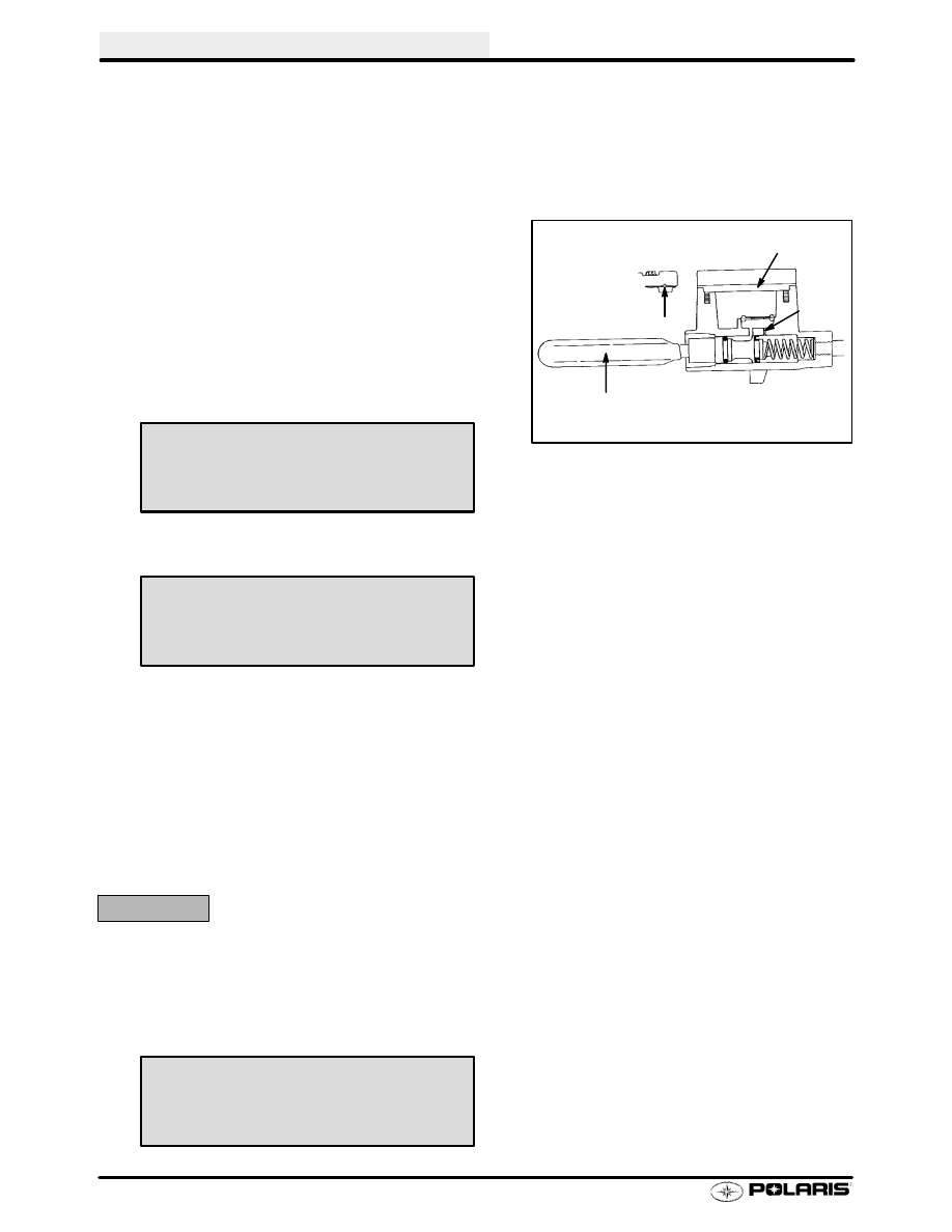
NOTE: Fluid may be forced from compensation port (B) when brake lever is pumped. Place diaphragm (C) in
reservoir to prevent spills. Do not install cover.

7.

Slowly pump lever (D) until pressure builds and holds.

8.

While maintaining lever pressure, open bleeder screw. Close bleeder screw and release brake lever. Do not
release lever before bleeder screw is tight or air may be drawn into caliper.

9.

Repeat procedure until clean fluid appears in bleeder hose and all air has been purged. Add fluid as
necessary to maintain level in reservoir.

CAUTION:

Maintain at least 1/2

(1.27 cm) of brake fluid in the reservoir to prevent air from entering the master cylinder.

10. Tighten bleeder screw securely and remove bleeder hose.

11. Add brake fluid to the proper level.

12. Install diaphragm, cover, and screws. Tighten screws to specification.

B

A

D

C

Mity Vac

PN 2870975

Polaris DOT 3 Brake Fluid

PN 2870990

Reservoir Cover Screw Torque -

15-18 in. lb. (1.7-2 Nm)

CHASSIS/BRAKES/FINAL DRIVE

5.9

Brake Bleeding - System Rebuild

Brake Bleeding - Fluid Change, Cont.

13. Field test machine before putting into service. Check for proper braking action and lever reserve. With lever

firmly applied, lever reserve should be no less than 1/2

(1.3 cm) from handlebar.

14. Check brake system for fluid leaks.

No Closer Than
1/2

(1.3 cm)

Brake Lever Reserve Limit

Not less than 1/2

(1.3 cm)

from handlebar

CHASSIS/BRAKES/FINAL DRIVE

5.10

Wilwood

t

t

t

t

System

Wilwood

t

Master Cylinder

1.

Cover Screws

2.

Cover

3.

Cover Gasket

4.

Parking Lever Spring

5.

Master Cylinder

6.

Screw

7.

Lever

8.

Pressure Switch

9.

Brake Line

10. Park Brake Lever
11. Reservior Ring

Wilwood

t

t

t

t

1.

Brake Caliper

2.

Kit Bleeder Replacement

3.

Brake Line

4.

Piston, Seal, Caliper Kit

5.

Brake Pads and Pin

1

2

3

4

5

6

7

8

9

10

11

2

1

3

4

5

CHASSIS/BRAKES/FINAL DRIVE

5.11

Hayes

t

Master Cylinder

1.

Cover Screw Kit

2.

Cover Asm. Kit (Incl. 1,3)

3.

Cover Gasket

4.

Parking Lever Spring

5.

Master Cylinder Assembly

6.

Screw

7.

Lever and Pivot Pin Kit

8.

Screw

9.

Body/Reservoir Clamp Kit

10. Brakelight Switch
11. Cartridge Kit
12. LH Control Asm
13. Pivot Pin Kit
14. Parking Lever and Spring Kit

Park Brake Lever Lock

WARNING

Release park brake lock before driving or brake sys-
tem failure or fire may result. Apply brake lever to re-
lease.

Hayes

t

Master Cylinder Removal

1.

Position clean shop cloths to catch spilled fluid.

CAUTION:

Brake fluid will damage finished surfaces. Do not allow brake
fluid to come in contact with finished surfaces.

2.

Remove the handlebar protector pad from the outlet end
of the handlebar master cylinder to access the brake fluid
line connector.

S

Remove handlebar cover strips

S

Remove two screws

S

Remove holding clip in front of cover

S

Remove handlebar pad

3.

Loosen the connector approximately 1/4 to 1/2 turn.

4.

Loosen and remove the four switch pack and handlebar
master cylinder mounting screws. Put screws aside for
later installation.

1

2

3

4

5

6

7

8

9

10

11

12

13

14


Content   ..  56  57  58  59   ..