Snowmobile Polaris High Performance (2001 year). Manual - part 51


  Index      Snowmobiles / ATV     Snowmobile Polaris High Performance - service manual 2001 year


Search            


Content   ..  49  50  51  52   ..


Snowmobile Polaris High Performance (2001 year). Manual - part 51


CLUTCHING

4.32

Assembly

1.

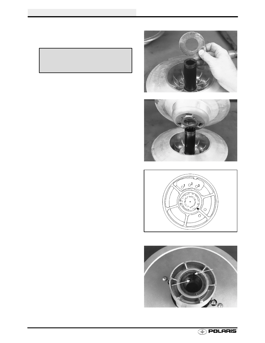
Install appropriate washer(s) on fixed shaft.

2.

Slide moveable sheave on fixed shaft.

3.

Install driven clutch spring. Be sure spring tab is
seated in hole in moveable sheave.

Refer to

specifications in front of this section for driven spring
setting.

S

P-85 driven clutches have 1 spring locat-
ing hole in the movable sheave and 4
holes in the helix.

NOTE: The driven clutch helix/moveable assembly has
several different spring locations which affect clutch shift-
ing and RPMs. Tighter spring tension will raise engine
RPMs during clutch upshift and allow quicker downshift
when pulling or negotiating a hill. The lighter tension posi-
tions will tend to have a slower downshift and a harder up-
shift.

4.

Align inner keyway between the helix and movable
sheave. With the spring in place, slide helix onto shaft
.5

(12mm).

Optional Thin Adjustment Washer (P-85)

.048

- PN 7555899

A

B

CLUTCHING

4.33

Assembly, Cont.

Helix Angles and Effects

The driven clutch helix was selected for overall performance in relation to the other driven system components. In
fine tuning situations requiring a slight adjustment of engine operating RPM or improved backshift, we
recommend trying a helix change before changing other components.

Helix Ramps*

The helix spring should always be adjusted within its limits before a helix change is performed. The normal rate of
change between helix angle steps is 250 RPM under full throttle. This is approximately the same result as in going
from the No. 1 to No. 4 spring position (P-85).
NOTE: Increasing spring tension increases engine RPM. RPM changes may not be evident if other drive or
driven clutch components are substandard.

* NOTE:

All R-Series, Mod(M), T1, and 40-36 helix ramps are cut 0.060

deeper in the snap ring pocket. These

are made so the driven clutch can open far enough for full shift out with wide 1 7/16

belts.If these helix ramps are

used with narrow belts, 2 (two) additional (for a total of three) .030

/.8 mm washers (PN 7556804) should be

installed under the snap ring to prevent the belt from touching the inner hub at full shift which can cause belt
failure.Wide belt models use only the existing washer under the snap ring.

5.

Hold fixed sheave and turn movable sheave 1/4 turn
counterclockwise.

6.

Force helix down into place, exposing snap ring
groove.

CLUTCHING

4.34

Assembly, Cont.

7.

Install spacer washer(s), and snap ring. Snap ring
should be installed with flat (machined) side up or
toward jackshaft bearing.

8.

Allow sheaves to close. Test clutch by pre-loading
movable sheave 1/4 turn counterclockwise and
releasing. Sheave should open and close smoothly
with a positive stop. Some helix ramps have more
than one washer beneath the snap ring.

NOTE: Always install snap ring with
chamfer towards helix (sharp edge out-
ward)

Preload
1/4 turn

Snap
Ring

Retainer

CLUTCHING

4.35

Installation

1.

Install proper number of spacer washers on jackshaft
between clutch and jackshaft bearing.
Inspect Jackshaft Bearing
Excessive vibration or abnormal drive belt wear can
be caused by a worn bearing or jackshaft on the driven
clutch side. To inspect bearing fit, watch the bearing
area closely as you try to force the jackshaft up and
down.

If

movement is detected, disassemble to

determine which parts are worn.

Replace the

jackshaft if the new bearing is loose on the shaft. The
bearing should be greased at 1000 mile (1600 km)
intervals and before storage.

NOTE: Spacer washers between driven clutch and jack-
shaft bearing set the offset. Refer to adjustment proce-
dure on page 4.40 to adjust offset between the drive and
driven clutch.

2.

Lightly grease jackshaft keyway or spline.

With

square key in place slide clutch onto jackshaft.

3.

Install spacer, bolt and washer to hold driven clutch in
place.

4.

P-85 driven clutches should float from side to side
(.040-.080

(1-2 mm)). Without a slight free float,

jackshaft bearings could be side loaded, causing
premature bearing failure.

Driven Clutch Retaining Bolt Torque-

15 ft. lbs. (21 Nm)

Driven Clutch Torque/Float

P-85 - .040-.100

(1-2.54 mm)


Content   ..  49  50  51  52   ..