Snowmobile Polaris (2006 year). Manual - part 39


  Index      Snowmobiles / ATV     Snowmobile Polaris - service manual 2006 year


Search            


Content   ..  37  38  39  40   ..


Snowmobile Polaris (2006 year). Manual - part 39


7.10

CLUTCHING

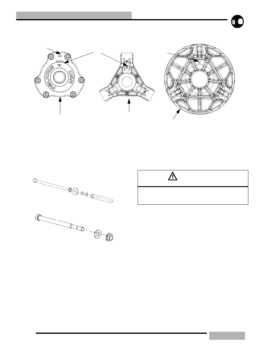
DRIVE CLUTCH IDENTIFICATION

Every clutch will have the last three digits of the clutch part 
number etched on to the cover (A). The “X" (B) marking is an 
index mark where the clutch cover (C), clutch spider (D) and 
the stationary sheave (E) should line up when the clutch is 
assembled.

DRIVE CLUTCH REMOVAL 

NOTE:  All clutch tools can be found at the 
beginning of this chapter. 

6.

Remove the belt See “DRIVE BELT” on page 7.4.

7.

Place the clutch holding tool (PN 9314177-A) on the drive
clutch.

8.

Remove the drive clutch retaining bolt. Note the
placement and number of washers that are on retaining
bolt.

9.

Place the correct clutch puller for the engine that you are
working on into the retaining bolt hole.

10. Tighten the puller into the clutch. If the clutch does not

come off, strike the clutch puller head with a hammer. If

the clutch does not “pop” off, continue to tighten the
clutch puller, and repeat this step.

A

B

C

D

B

E

Domestic

Fuji

CAUTION

Do not use a impact wrench to remove or install the 

clutch bolt or clutch puller. Damage to the clutch and/or 

crankshaft can occur.

7.11

CLUTCHING

DRIVE CLUTCH COMPONENTS

NOTE:  Replacement clutches come complete and balanced without clutch weights and clutch spring. The 
clutch cover, spider, and sheaves cannot be purchased separately as replacement parts.

7.12

CLUTCHING

1

1

2

3

4

5

6

7

18

17

10

8

9

13

12

11

15

16

14

7.13

CLUTCHING

DRIVE CLUTCH DISASSEMBLY

1.

In a straight line, mark the sheaves and the cover with a
black marker (1).

2.

Remove the clutch. See “DRIVE CLUTCH REMOVAL”
on page 7.10

3.

Place the drive clutch in the clutch compression tool (PN

8700220).

4.

Compress the clutch in the compression tool and lock the
compression tool, making sure that all cover bolts (2) are
accessible.

5.

Remove the cover bolts and washers (2) evenly and
carefully. Do not allow side loading or misalignment of the
cover (3), or the bushing (4) can be damaged. 

6.

Carefully remove the tension from the compression tool.

7.

Remove the cover (3) and inspect the cover bushing (E)
and replace it if it is damaged or worn.

8.

Remove the spring (5).

NOTE:  Replace the cover bushing if the inside 
diameter is over 1.40” (28.95mm)

9.

Mount the drive clutch securely in a drive clutch holding
fixture (PN 2871358).

10. Remove the jam nut (6) in a counterclockwise direction

(standard thread) using the drive clutch spider nut socket
(PN 2871358).

11. Install the spider removal tool (PN 2870341), and remove

the spider (7) in a counterclockwise direction (standard
thread).

12. Measure the total thickness of the spacer washers (18) that

are installed under the stepped washer (17) and record the
thickness of these spacer washers. Make sure that you note
that the stepped washer is on the top of the spacer stack.

13. Inspect both sheave surfaces (8,10) for wear or damage.

14. Inspect the moveable sheave bushing (9) for wear or

damage.

15. Remove all three drive clutch weights (13).

16. Inspect each weight. The surface should be smooth, with

no waves or galling. Place bolt inside weight to check
flyweight bushing and pin surface for wear by rocking the
weight back and forth.

17. Inspect all the rollers (15), bushings (16) and roller pins

(14) by pulling a flat metal rod across the roller.

18. Roller can also be inspected by rolling with a finger to feel

for flat spots, roughness, or loose bushing.

NOTE:  The flyweight bushing is not replaceable. If 
flyweight bushing is damaged both the flyweight, pin 
and nut will need to be replaced. 

19. Also inspect to see if the roller and bushing are separating.

20. Bushing must fit tightly in roller.

21. Replace roller and pin if roller fails to roll smoothly (no flat

spots) or if the bushing is loose or worn.

22. Assembly is the reverse order of disassembly. Note the

specifications and notes in See “Drive Clutch Service
Components” on page 7.13

CLUTCH ASSEMBLY

1.

Assemble the rollers, bushings and roller pins if they were

Table 7-3: Drive Clutch Service Components

ITEM

DESCRIPTION

TORQUE SPECIFICATION/

NOTES

1

Index mark

2

Cover bolts and washers

90in-lb (10Nm)

3

Clutch cover

4

Cover bushing

5

Clutch spring

6

Spider nut

7

Spider

8

Moveable sheave

9

Moveable sheave bushing

10

Stationary sheave

11

Clutch weight pin nut

This should facing the trailing 

side of the clutch

12

Clutch weight pin

This should be facing the 
leading side of the clutch

13

Clutch weight

14

Pin

15

Roller

16

Shim

17

Stepped washer

Make sure that the stepped 

washer is on top of the washer 

stack and that the washer has 

the step facing the sheave side.

18

Washer stack

CAUTION

Eye protection must be worn during disassembly.

CAUTION

Sheaves must be marked to provide a reference point 

for dutch balance and spider indexing. If the sheaves 

are not marked and the spider washers are changed or 

misplaced, the clutch will be out of balance and dam-

age to the clutch may result. 

WARNING

Clutch spring is under extreme tension, use caution 

when disassembling the clutch.


Content   ..  37  38  39  40   ..