Challenger Terra Gator 3244 Chassis. Manual - part 99
Page 35
Section 4
Assembly
•
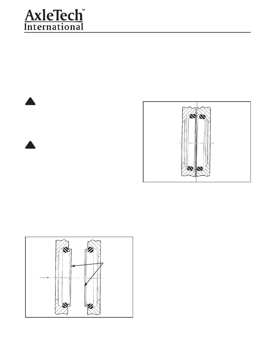
If the seals are not aligned correctly:
The
seals will move. Any wobbling motion of the
seals is an indication of incorrectly positioned
(cocked) seals. Dirt can enter past the Toric
Ring.
•
Shown in Figure 4.26, the Toric Rings have
slipped, instead of rolling on the left-hand side
of the seal. Note how the top Toric Ring is to
the right and the bottom Toric Ring is to the left.
The same seals are also shown after the bot-
tom half is rotated 90 degrees.
•
If the Toric Ring slips at any location,
it will
twist, causing the formed seal rings to seat
incorrectly (cock).
4. Install the hub. Use a large thin-wall tube (tool
number 1, see Special Tool Section), to push the
inner bearing onto spindle while installing hub
onto spindle.
Figure 4.26
Wheel Hub to Spindle Assembly
NOTE:
Complete the assembly of the wheel hub to
the spindle. Before installing the wheel hub onto the
spindle, however, keep the following points in mind to
ensure correct sealing between the faces of the Toric
Ring:
1. Check both sealing faces carefully to make sure
they are clean and free of any dirt, debris, lint, and
even human hair.
CAUTION
Bring the housings together slowly. High impact
can result in component damage. Remove protec-
tive pad from the spindle's seal journal.
2. Remove the protective pad from the spindle's seal
journal.
CAUTION
Do not apply lubricant to the Toric Ring. The Toric
Ring can leak. Damage to components
can result.
3. Apply a light coating of Dow Corning GN molybde-
num assembly paste lubricant to the two mating
surfaces of the face seal’s steel rings only. Do not
allow this lubricant to contact the Toric Ring. The
Toric Ring can leak. Figure 4.25.
•
When installing the hub onto the spindle, both seal
housings must be aligned correctly.
•
Slowly bring the hub and spindle assembly togeth-
er as the spindle bearing adjustment nut is tight-
ened. Figure 4.25.
!
!
Figure 4.25
FACE SEAL
MATING
SURFACES