Challenger Terra Gator 3244 Chassis. Manual - part 98


  Index      Challenger     Challenger Terra Gator 3244 Chassis - service repair manual 2009 year


Search            


Content   ..  96  97  98  99   ..


Challenger Terra Gator 3244 Chassis. Manual - part 98


Page 31

4. A piece of thin shim stock ~0.0254mm (0.001”) is

to be inserted in several places around the 

diameter to check the ring gear is properly seated.

5. Install (2) bolts, nuts and washers, for safety.
An optional assembly method is as follows if a press

is not used:
1. Apply a light coat of grease to the O-Ring.
2. Install the O-Ring into the groove of the planetary

ring gear face. Care should be taken not to twist or

damage the O-Ring during assembly.

3. Apply a light coat of oil to the outer diameter edge

of the planetary ring gear that will be pressed into

the spindle flange bore.

4. Set the spindle over the planetary ring gear and 

O-Ring already assembled and align the holes in

the spindle flange with the planetary ring gear

spacing by using 1 or 2 temporary guide pins that

fit the M18 holes.

CAUTION

Do not use a steel hammer, use a rubber or
rawhide mallet.
5. Using a rubber or rawhide mallet, Not Steel 

hammer,tap the spindle over the planetary ring

gear by hitting around the spindle flange several

times until ring gear is seated. 

6. Remove the temporary guide pins. 
7. A piece of thin shim stock ~0.0254mm (0.001”) is

to be inserted in several places around the 

diameter to check the ring gear is properly seated.

Wheel Hub, Inner Bearing Spacer,
Wheel Bearings, Seal, and Spindle
Sub-Assembly

If the wheel hub,spindle, and bearings were 

disassembled during disassembly, the following 

procedure is recommended. Figure 4.15.

!

WARNING

Observe all warnings and cautions provided by
the press manufacturer to avoid damage to 
components and serious personal injury.
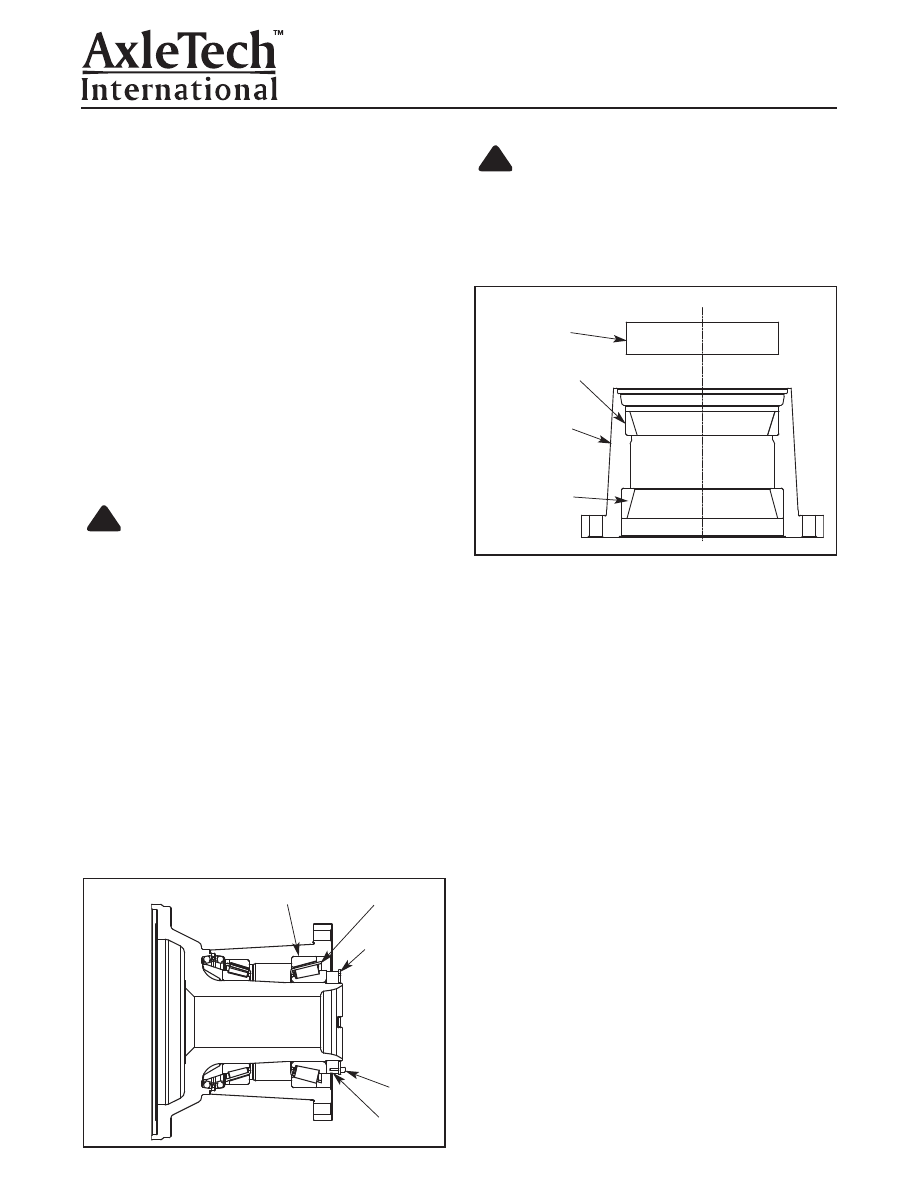
1. Place the wheel hub upright in a press to install the

bearing cups. Figure 4.16.

2. Press each bearing cup into the wheel hub against

the shoulder in the wheel hub by using the appropri-

ate bearing cup drivers, tool number 2 and 3 (see

Special Tool Section).

3. A piece of thin shim stock ~0.0254mm (0.001”) is

to be inserted in several places around the diame-

ter to check the bearing cups are properly seated.

4. Remove the wheel hub from the press and place

on suitable workbench for further safe assembly.

NOTE:

The inner bearing cone must be installed in

the wheel hub and not on the spindle bearing 

diameter because the Duo Cone seal, once installed

in the wheel hub assembly will not fit over the bearing

cone assembly.
5. Apply a light coat of oil to the inner bearing cone

rollers and install in the wheel hub assembly.   

6. If the wheel bearing spacer was previously

removed, apply Adhesive #Q58-Grade -226 or

#Q44 to the spindle face of the bearing spacer.

Figure 4.17.

!

Figure 4.16

Figure 4.15

Section 4

Assembly

OUTER BEARING CUP

BEARING

CONE

LOCKPLATE

CAPSCREW

ADJUSTING NUT

PRESS TOOL

BEARING CUP

WHEEL HUB

BEARING CUP

7. Slide the spacer over the spindle and against the

spindle shoulder tapping with a brass rod to 

properly seat the wheel bearing spacer. Alternatively,

a large, thin-wall tube (tool number 1, see Special

Tool Section) for installing the inner bearing onto the

spindle during hub assembly, could be used to push

the bearing spacer onto the spindle. 

Page 32

Section 4
Assembly

1.  Seal Ring

5.  Seal Ring Housing

2.  Toric Ring

6.  Seal Ring Face

3.  Housing Retainer Lip

7.  Installation Tool (TC-79461)

4.  Housing Ramp

Figure 4.18

1

2

3

4

5

7

6

Toric Ring Face Seal into 
Hub and into Spindle

CAUTION

Install face seal halves in the same positions
where they were located prior to disassembly.
Mixing up face seal halves can cause component
damage.

The TRS Toric Ring face seal halves must be

installed in the spindle and in the hub before the hub

can be assembled to the spindle. Figure 4.18. Install

the Toric Ring face seal halves in the spindle and in

the hub as follows:

!

WARNING

Solvent cleaners can be flammable, poisonous
and cause burns. Examples of solvent cleaners
are carbon tetrachloride, emulsion-type cleaners
and petroleum-base cleaners. To avoid serious
personal injury when you use solvent cleaners,
you must carefully follow the manufacturer’s
instructions and these procedures:

Wear safe eye protection.

Wear clothing that protects your skin.

Work in a well-ventilated area.

Do not use gasoline, or solvents that contain
gasoline. Gasoline can explode.

You must use hot solution tanks or alkaline
solutions correctly. Carefully follow the manu-
facturer’s instructions.

CAUTION

Check for solvent residue on all seating surfaces.
Solvents that leave a residue on the Toric Ring,
metal face seal or on housing seal seating sur-
face can cause the Toric Ring to roll into the seal,
rather than slide. Damage to the seal can result.

1.  Make sure the formed seal ring, Toric Ring and

wheel hub are clean and free of any oil or other

contaminants. If required, use a solvent like iso-

propyl alcohol, that evaporates quickly, leaves no

residue, and is compatible with the Toric Ring.

CAUTION

Install the Toric Ring into the seal ring and make
sure it is flat. Do not twist the Toric Ring when
installing onto the seal ring. A twisted Toric Ring
will not seal correctly, allowing leakage of lubri-
cant and pumping of debris past the ring.
Damage to components can result.

2.  Install the Toric Ring onto the formed seal ring so

that it rests in the radius of the tail of the seal ring

and is not twisted. Install the Toric Ring onto the

seal ring as follows:

!

!

!

Figure 4.17

SPINDLE

BEARING

SPACER

Page 33

Section 4

Assembly

CAUTION

Do not use Stanosol

®

or any other liquid that

leaves an oily film and does not evaporate quickly,
since this may result in incorrect seating of the 
O-ring in the housing, resulting in seal leakage.

3.  Coat the Toric Ring with isopropyl alcohol so that

it slides easily past the retainer lip in the wheel

hub and installs correctly on the spindle ramp.

Figure 4.21.

4.  Place installation tool part number TC-79461 (see

Special Tool Section) around the metal seal ring

and Toric Ring. Installation tools are available

from AxleTech International at in North America 

1-877-547-3907, in Europe 33-477-92-8868 or 

at www.axletech.com/aftermarket.htm.

5.  Wipe the O-ring with a lint-free towel or clean

foam brush saturated with isopropyl alcohol.

6.  Shake excess lubricant from the assembly.

Immediately install (“pop”) the seal into the wheel

hub with a firm push of the installation tool.

Figure 4.21.

7.  Remove the installation tool.

!

Figure 4.21

CAUTION

Do not use Stanosol

®

or any other liquid that

leaves an oily film and does not evaporate quick-
ly, since this may result in incorrect seating of
the Toric Ring in the housing, resulting in seal
leakage.

A.  Wet the rubber Toric Ring with isopropyl alco-

hol and install it onto the formed seal ring so

that it is seated at the bottom of the seal ring

ramp and against the retaining lip. Figure 4.19.

B.  Make sure the Toric Ring is not twisted by 

rapidly pulling it away from the seal ring and

letting it snap back. Do this in a number of

places until the seal is correctly seated.  Be

careful not to nick or cut the Toric Ring seal,

as this will cause leaks. Figure 4.20.

!

1.  Seal Ring Ramp

3.  Seal Ring Retaining Lip

2.  Rubber Toric Ring

4.  Seal Ring

Figure 4.19

4

3

1

2

Figure 4.20

Page 34

Section 4
Assembly

2.  If required, adjust the seal standout height by

using the following methods.

If the standout height cannot be brought into
specification:

Remove the seal and repeat the

installation procedure.

CAUTION

Push or pull the Toric Ring and face seal only.
Do not push or pull directly on the seal ring. This
can cause component damage.

A.  Use the installation tool to push down on the

Toric Ring and face seal.

B.  With your fingers, pull up uniformly on the

Toric Ring and face seal.

CAUTION

Apply isopropyl alcohol to the Toric Ring. Check
the retaining lip of the seal seating area for burrs
or fins, which can cause a seal to leak. Damage
to components can result.

3.  Apply isopropyl alcohol as a lubricant to the Toric

Ring and place in the seating area. If installation

does not appear smooth, flat and correct, remove

the seal from the spindle and repeat the process.

CAUTION

To prevent slippage of the Toric Ring, allow suffi-
cient evaporation time for the assembly lubricant
before proceeding with further assembly.
Damage to components can result.

4.  Seat Toric Ring correctly. Once correctly in place,

the Toric Ring must roll on ramp only. See 

Figure 4.24 

for examples of incorrect installation.

!

!

!

Figure 4.24

8.  Follow the same procedure to install the other half

of the face seal assembly onto the wheel spindle.

Figure 4.22.

Check for Correct Installation of the 
TRS Toric Ring Seal

Check the spindle and wheel hub for correct installa-

tion of the TRS Toric Ring face seal before the hub

can be installed onto the spindle. 
1.  Check assembled height variation (A) in at least

four places, 90 degrees apart, using a caliper,

toolmaker’s rule, or other accurately calibrated

measuring device. The difference in height

around the ring must not be more than 0.5 mm

(0.02 inch). Figure 4.23.

A

Figure 4.23

Figure 4.22


Content   ..  96  97  98  99   ..