Aprilia scooter (manual) - part 13
-
THROTTLE BODY
-
REMOVING THE THROTTLE BODY
-

-
Remove engine inspection cover, see (REMOVING THE HELMET COMPARTMENT).
-
Place a cloth under fuel supply hoses (1) to avoid any fuel spilling.
-
Disconnect fuel supply hoses (1) delivering and returning toIfrom injector.
-
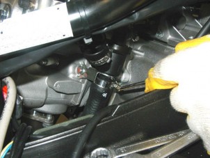
Loosen and remove securing screw (2) of fuel hoses clamps.
-
Disconnect electric connection (3) controlling the injector.
-
Loosen clamp of air box intake manifold.


-
Disconnect electric connection (4) of stepper motor.
-
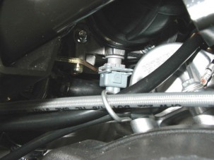
Disconnect electric connection (5) of throttle positioning sensor.

-
Loosen and remove the three securing screws (6) of intake manifold (7) to the head.
-
Remove intake manifold (7) with throttle body (8).

-
Disconnect electric connection (9) of air temperature sensor.

-
Loosen both securing nuts (10) of hose guides to carburettor support.
-
Withdraw hose guide and its retainer (11) of forward stroke control on carburettor.
-
Withdraw hose guide and its retainer (12) of return stroke control on carburettor.

-
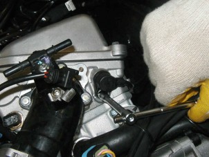
Loosen and remove the three securing screws (13) of throttle body (8) to intake manifold (7).
-
Disassemble throttle body (8) from intake manifold (7).
-
Loosen and remove securing screw (14) of injector
(15) to intake manifold.
-
Remove injector (15) of intake manifold (7).
-
ENGINE
-
REMOVING THE ENGINE
 WARNING
Before performing following operations, engine
shall be removed from the frame from the back side; then provide and arrange all necessary tools.
NOTE Where a procedure is cross-referred to relevant sections in the manual, proceed sensibly to avoid disturbing any parts unless strictly necessary.

The operations to disassemble engine from frame are listed below.
-
-
-
Remove helmet compartment, see (REMOVING THE HELMET COMPARTMENT).
-
Disconnect fuel delivery hoses (1).
-
Release and remove clamps screw (2).
-
Disconnect the injector connector (3).

-
Disconnect connector of stepper motor (5).
-
Disconnect connector of throttle position sensor (4).
-
Disconnect air sensor on throttle body.


-
Loosen both securing nuts (6) of hose guides to carburettor support.
-
Withdraw hose guide and its retainer (7) of forward stroke control on carburettor.
-
Withdraw hose guide and its retainer (8) of return stroke control on carburettor.
-
Disconnect coolant temperature sensor.


-
Unscrew and remove securing screw of timing sensor.
-
Close sensor seat with a cloth to prevent that any foreign matter get into cylinder head.

-
Cut clamps and release timing sensor cable.
-
Remove timing sensor from crankcase and place it in a safe position.

-
Remove the spark plug cap.


-
Unscrew and remove securing screw and collect ground cables.

-
Unscrew and remove connection nut on starter motor.
-
Withdraw the cable from starter motor.
-
Disconnect oil pressure sensor.

-
Cut the clamps.


-
Loosen the clamp and remove exhaust silencer.
-
Unscrew and remove the three screws (9).


-
Unscrew and remove both securing screws of brake calliper (10) and the screw (11) of hose guide.
-
Move the rear brake calliper.
-
Loosen the clamp.


-
Withdraw upper hose from coolant pump and collect the coolant in a suitable container.
-
Loosen the clamp.
-
Withdraw the hose from thermostatic valve.

-
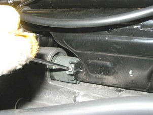
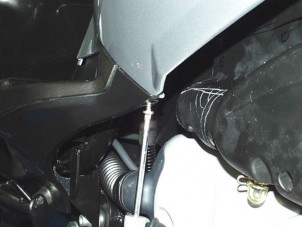
Fasten the A frame belt to the frame lower side as shown in the figure and lift slightly the bike rear side.
-
Unscrew and remove lower securing screw in both shock absorbers.
-
Unscrew and remove securing nut of crankcase pin.


-
Unscrew and remove the screw and loosen ring nut.

-
Take out engine pin from the right side.
-
Move frame forward and release crankcase.
-
REASSEMBLING THE ENGINE ON THE FRAME

-
-
Position crankcase near engine pin fitments on the frame
-
Insert engine pin from the right side.
-
Position ring nut properly and tighten securing screws.
-
Tighten securing nut of engine pin.


-
Lower the frame as shown in the figure until shock absorber fitments are matching.
-
Tighten lower securing screw in both shock absorbers.

-
Fit the hose on thermostatic valve.
-
Tighten clamp.

-
Position upper hose on coolant pump and tighten clamp.
-
Fill the cooling system, see (ATLANTIC 125 200 WORKSHOP MANUAL)

-
Refit brake calliper
-
Tighten both securing screws of brake calliper (1) and the screw (2) of hose guide.

-
Position exhaust tail pipe and tighten the three securing screws (3)
-
Tighten the clamp


-
Position oil pressure sensor.
-
Fit clamps to ensure a perfect fixing of oil pressure sensor cable.

-
Position cables on starter motor.
-
Tighten securing nut.

-
Position ground cables.
-
Tighten securing nut.
-
Position the spark plug cap.

-
Fit timing sensor in its seat.
-
Tighten securing screw of timing sensor.
-
Fit clamps to ensure a perfect fixing of timing sensor cable.
-
Position coolant temperature sensor.


-
Position hose guide and its retainer (4) of return stroke control on throttle body.
-
Position hose guide and its retainer (5) of forward stroke control on throttle body.
-
Tighten both securing nuts (6) of hose guides to throttle body support.
-
Disconnect air sensor on throttle body.

-
Disconnect connector of throttle position sensor (7).
-
Disconnect connector of stepper motor (8).

-
Connect the injector connector (9).
-
Tighten the clamps screw (10).
-
Connect the injector connector (11).
-
CHASSIS
-
REMOVING THE BATTERY COVER

-
-
-
Raise the seat.
-
Loosen and remove the four screws.
-
Lift battery cover.
-
Remove under seat light bulb from its seat.


-
Disconnect power outlet connector.
-
Remove battery cover.
-
REMOVING THE TAIL GUARD

-
-
Remove luggage rack, see (ATLANTIC 125 200 WORKSHOP MANUAL)
-
Remove both under seats, see (ATLANTIC 125 200 WORKSHOP MANUAL)
-
Working on either side, loosen and remove the three upper screws.
-
Working on either side, loosen and remove the lower screw.
-
Unscrew and remove the lower centre screw.


-
Release and remove the two lower side screws.
-
Move tail guard and disconnect rear light connector.

-
Disconnect the seat releasing cable.


-
Withdraw the two electric components from the hooks
-
Remove complete tail guard.
-
REMOVING THE HELMET COMPARTMENT

-
-
Remove the tail guard, see (REMOVING THE TAIL GUARD).
-
Remove the seat, see (ATLANTIC 125 200 WORKSHOP MANUAL).
-
Remove the battery cover, see (REMOVING THE BATTERY COVER).
-
Remove the battery.
-
Loosen and remove the two front screws.
-
Loosen and remove the two rear screws.


-
Loosen and remove the four CPU screws.
-
Move the CPU and collect the ground cable.

-
Remove the bank angle sensor.

-
Unscrew and remove the five securing screws and collect the nut.

-
Loosen and remove the two screws.
-
Remove helmet compartment casing.

-
Unscrew and remove the seven securing screws of engine inspection cover.
-
Remove engine inspection cover.

-
Remove primary and auxiliary fuse carrier from the hooks.
-
Remove helmet compartment.
-
REMOVING THE SHOCK ABSORBER

-
-
Remove the tail guard, see (REMOVING THE TAIL GUARD).
-
Unscrew and remove upper securing screw.

-
Unscrew and remove lower securing screw.
-
Remove shock absorber.
-
ELECTRIC SYSTEM
-
WIRING DIAGRAM
-

Key:
-
Multiple connectors
-
Low fuel light
-
High beam warning light
-
Parking light warning light
-
Instrument panel backlighting
-
EFI light
-
Right direction indicator warning light
-
Left direction indicator warning light
-
Oil pressure light
-
ABS light (not in use)
-
Side stand light
-
Antitheft system LED
-
Fuel level gauge
-
Water temperature gauge
-
Complete instrument panel
-
Oil pressure sensor
-
Warning horn
-
Repeater
-
Direction indicator switch
-
Left dimmer switch
-
Horn button
-
Rear brake switch
-
Complete headlight
-
Radio power supply
-
Auxiliary fuses label
-
Protection diode for alarm
-
Fuel level
AUXILIARY FUSES:
-
15 A INJECTION, BRAKE LIGHTS, STARTING.
-
3A LOGIC I ENGINE KILL
-
15A LIGHTS, HORN, INSTRUMENT PANEL, FAN RELAY, REPEATERIDIRECTION INDICATORS, INSTRUMENT PANEL, RADIO, FUEL LEVEL ECU
-
15A POWER SOCKET
-
3A ECU PERMANENT POWER SUPPLY
-
SPARE
-
15A SPARE FUSE H 3A SPARE FUSE I SPARE
WIRE COLOUR CODING
|
23. |
Fan relay |
Ar |
Orange |
||
|
24. |
Starter button |
Az |
Light blue |
||
|
25. |
Engine kill switch |
B |
Blue |
||
|
26. |
Front brake switch |
Bi |
White |
||
|
27. |
Bank angle sensor |
G |
Yellow |
||
|
28. |
Key operated switch |
Gr |
Grey |
||
|
29. |
Compartment light |
M |
Brown |
||
|
30. |
Compartment light switch |
N |
Black |
||
|
31. |
Right parkingIstop lights |
R |
Red |
||
|
32. |
Left parkingIstop lights |
Ro |
Pink |
||
|
33. |
Number plate light |
V |
Green |
||
|
34. |
Rear left turn indicator |
Vi |
Violet |
||
|
35. |
Rear right turn indicator |
||||
|
36. |
Antitheft system control unit |
||||
|
37. |
Auxiliary fuses |
||||
|
38. |
Starter motor |
||||
|
39. |
Starter relay |
||||
|
40. |
Battery |
||||
|
41. |
Main fuses |
||||
|
42. |
Power outlet |
||||
|
43. |
Flywheel |
||||
|
44. |
Voltage regulator |
||||
|
45. |
Fan |
||||
|
46. |
Instrument panelIengine |
water |
temperature |
||
|
thermistor |
-
Instrument panel air temperature thermistor
-
Throttle sensor
-
Oxygen sensor (not as standard)
-
Side stand switch
-
Auxiliary injection relay
-
Main injection relay (polarised)
-
Fuel level sensor
-
Fuel pump
-
Fuel injector
-
Coil
-
Spark plug
-
Stepper motor
-
RPM sensor
-
ECU diagnosis socket
-
ECU
-
Front left turn indicator
-
Parking light
-
High beam lamp
-
Low beam lamp
-
Front right turn indicator