Aprilia scooter (manual) - part 11
-
REAR TOP BOX LIGHT SWITCH TEST
-
Raise the saddle and check continuity across the two terminals with a multimeter set to the Ohm range.
Correct reading when switch is released (saddle raised) : 0 ohm
Correct reading with switch pressed (saddle closed):
ohm
-
LIGHT CIRCUIT
-
LIGHT CIRCUIT
-

Key:
2. High beam light
-
Parking lamp light
-
Dashboard backlighting bulbs
15. Complete dashboard
18. Left switch
21. Key-operated switch
27. Parking light/left brake light
29. Parking light /right brake light
32. Number plate light
38. Main fuses
-
Battery
-
Auxiliary fuses
-
High beam lamp
-
Low beam lamp
-
Parking light
-
Complete headlight

TROUBLESHOOTING
-
Check battery condition, 2.4.1.
-
Check fuse condition, 8.12.1.

-
Check the light switch
-
Check the bulbs, 8.11.1.
SWITCH TEST
-
-
Check switch continuity using a multimeter.
-
Change any switch that operates other than as specified in the relevant diagram.
Light switch
Wires
V
N
Bi
V


PAS


-
VISUAL AND ACOUSTIC SIGNALS
-
VISUAL AND ACOUSTIC SIGNALLING SYSTEM
-
Key:
-
Right indicator light
-
Left indicator light
15. Complete dashboard
-
Warning horn
-
Horn button
-
Key-operated switch
-
Direction indicator switch
26. Rear left direction indicator
30. Rear right direction indicator
38. Main fuses
-
Battery
-
Auxiliary fuses
45. CDI control unit
54. Front right direction indicator

DIRECTION INDICATOR TROUBLESHOOTING
-
-
Check that the bulbs are in good condition, 8.11.1.
-
When one bulb is burnt out, the other bulb will flash at doubled frequency.
-
Check the direction indicator switch.

-
Check the CDI control unit and replace if needed,
7.2.2.
The flasher is incorporated into the CDI control unit.


WARNING HORN TEST
-
Feed 12 Volts to the two connectors of the waning horn.
-
If the horn does not operate, adjust through the adjuster.
-
Replace the horn if necessary.
SWITCH TEST
-
Check switch continuity using a multimeter.
-
Change any switch that operates other than as specified in the relevant diagram.
Direction indicator switch
Wires
B/N
Az
r
Left direction indicator

Right direction indicator

Horn button
Wires
Gr
V
ON

OFF
-
BULB REPLACEMENT


-
BULB REPLACEMENT Read 1.2.1., 1.7.1. carefully.
-
 WARNING
Before proceeding to change a bulb, rotate the

ignition switch to “ ”.Wear clean gloves or use a clean, dry cloth to handle bulbs. Do not put your fingerprints on a bulb, as this may cause overheating leading to failure. If you touch a bulb with your fingers, remove any fingerprints with alcohol to avoid early failure. DO NOT PULL ON THE WIRING.

-
-
Place the vehicle on the stand.

NOTE Check the fuses before changing a bulb, 8.12.1.
PARKING LIGHT BULB

To replace:
-
Remove the front cover, 7.1.10.
 WARNING
Proceed carefully.
Do not damage the tabs and/or their recesses.
-
Rotate and extract the bulb holder working from the rear end of the bulb holder.
-
Extract the bulb.
NOTE Make sure the locating pegs locate properly into the holder when fitting the bulb.
-
Fit a new bulb of equal rating.

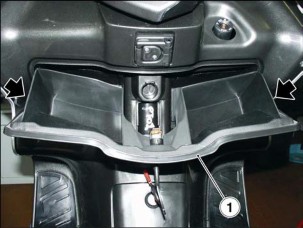
HIGH AND LOW BEAM BULBS
To replace:
Open the glove compartment (1) and unhook the side guides pressing moderately down.


-
Grasp the bulb connector (2) and pull to disconnect.
-
Twist the bulb holder (3) anticlockwise and extract from the reflector seat.
-
Extract the bulb.
On refitting:
NOTE Insert the bulb into the reflector seat and ensure that the three pegs on the bulb match the slots in the reflector seat.
-
Position the bulb holder (3) into the reflector seat and twist clockwise.
-
Connect the bulb connector (2).

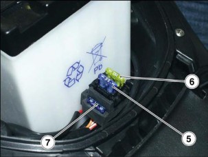
TAIL LIGHT BULBS
The tail lights accommodate:
-
Two parking light/brake light bulbs (4).
-
Two rear direction indicator bulbs (5).
NOTE The following procedure applies to both indicators.

To replace:
-
-
Unscrew the two retaining screws (6) and remove the lens (7).
 WARNING
Proceed carefully.
Do not damage the tabs and/or their recesses.

-
Rotate anticlockwise and extract the bulb (4, parking/brake light) or (5, direction indicator).
-
Fit a new bulb of equal rating.
NOTE On refitting, ensure the lens (7) locates properly into its seat.
 WARNING
Proceed carefully.
Do not damage the tabs and/or their recesses.
-
Tighten the screws (6) gradually. Do not overtighten or you will damage the lens (7).

FRONT DIRECTION INDICATOR BULBS

-
Remove the front cover, 7.1.10.
-
Working from the front end of the vehicle, rotate the holder (8) with the bulb (9) clockwise and extract both.
-
Press the bulb (9) moderately and twist anticlockwise.
-
Extract the bulb.
NOTE Make sure the locating pegs locate properly into the holder when fitting the bulb.
-
Fit a new bulb of equal rating.

TAIL LIGHT BULB
-
Grasp the bulb holder (10), pull and extract.
-
Remove the bulb and fit a new bulb of equal rating.


DASHBOARD BULBS
-
Remove the dashboard, 7.2.6.
-
Rotate the bulb holder clockwise and extract.
-
Extract the bulb – which is the bayonet type – and replace it.
-
Insert the bulb holder and rotate clockwise to lock it in place.

CLOCK BATTERY REPLACEMENT

-
Remove the dashboard to give access to the rear end,
7.2.6.
-
Release the click-opening door.
-
Change the button battery.
-
Refit the click-opening door.

-
REPLACING THE FUSES
-
REPLACING THE FUSES
 WARNING
-
Never attempt to repair a defective fuse.
Never use a fuse of a rating other than specified.
This could damage the electrical system or cause a short circuit, with the risk of fire.
NOTE When the fuses fitted in a particular position keep blowing frequently, there might be a short circuit or overloading.
Checking the fuses is recommended whenever an electrical component fails to operate or is malfunctioning, or when the engine does not start.

Check the 3-A and 15-A fuses first and then the 30-A fuses.

-
-
Set the ignition switch to “ ”. This will prevent accidental short circuits.
Main fuses:

-
Perform the first four steps described at paragraph
2.4.3.

Auxiliary fuses:
-
Remove the front cover, 7.1.10.
Inspection:
-
Extract all fuses one by one and check for blown fuses. A blown fuse is identified by the link bar in the centre being divided.
-
When you find a blown fuse, determine and rectify the cause (if possible) before fitting a new fuse.

-
Replace any failed fuse with a fuse of equal current rating.
NOTE When you use one of the spare fuses, remember to add a new fuse of equal rating to the fuse box.
Layout of auxiliary fuses (front cover):
- 15-A fuse (1)
From ignition switch to: lights, horn, brake lights.
- 7.5-A fuse (2)
From ignition switch to: starting interlock relay, automatic starter.
- 7.5-A fuse (3)
Spare.
- 15-A fuse (4)
Spare.
Layout of main fuses (battery compartment):
- 20-A fuse (5)
From battery to: ignition switch, helmet compartment light.
- 15-A fuse (6)
From battery to: power socket.
- 15-A fuse (7)
Spare.

10 m
8.13. BEAM SETTING
This is a quick beam inspection procedure. Place the vehicle ten metres away from a vertical wall. It is important that the motorcycle be on level ground.
Switch on the low beam and sit astride the vehicle. The light spot on the wall should be just below the horizontal line of the headlight (about nine/tenths of overall height).

To set beam height:
-
Open the glove compartment (1) and unhook the side guides by pressing moderately downwards.

-
Use a screwdriver and rotate the lower adjuster screws
(2) of both beams:
TIGHTEN (turn clockwise) to lower the beam. SLACKEN (turn anticlockwise) to raise the beam.
![]()
8.13.2. BEAM HORIZONTAL SETTING
To adjust the horizontal position of the beam:
-
Open the glove compartment (1) and unhook the side guides by pressing moderately downwards.

-
Use a screwdriver and rotate the upper adjuster screws (2) of both beams:
TIGHTEN (turn clockwise) to move the beam to the right (viewed in the direction of travel);
SLACKEN (turn anticlockwise) to move the beam to the left; (viewed in the direction of travel).
![]()
-
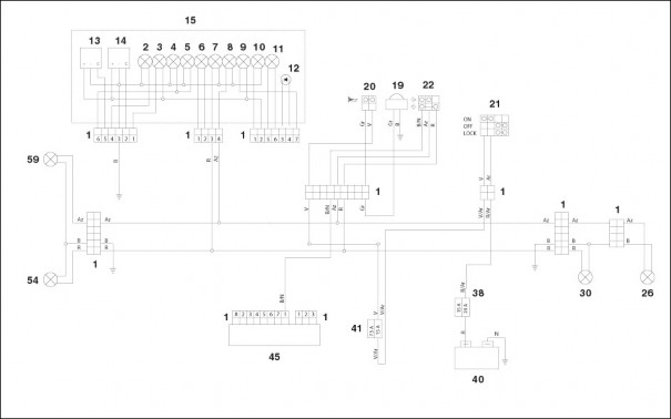
WIRING DIAGRAM
-
WIRING DIAGRAM
-

Key:
WIRE COLOUR CODING
|
1. |
Multi-pin connectors |
Ar |
Orange |
|
2. |
High beam warning light |
Az |
Light blue |
|
3. |
Low fuel light |
B |
Blue |
|
4. |
Parking light warning light |
Bi |
White |
|
5. |
Dashboard backlighting bulbs |
G |
Yellow |
|
6. |
Check light (not in use) |
Gr |
Grey |
|
7. |
Right direction indicator repeater light |
M |
Brown |
|
8. |
Left direction indicator repeater light |
N |
Black |
|
9. |
Oil pressure light |
R |
Red |
|
10. |
ABS light (not in use) |
Ro |
Pink |
|
11. |
Side stand light |
V |
Green |
|
12. |
Anti-theft system LED (not in use) |
Vi |
Purple |
|
13. |
Coolant temperature indicator |
||
|
14. |
Fuel level indicator |
||
|
15. |
Complete dashboard |
||
|
16. |
Coolant thermistor |
||
|
17. |
Oil pressure sensor |
||
|
18. |
Left light switch |
||
|
19. |
Warning horn |
||
|
20. |
Horn button |
||
|
21. |
Key-operated switch |
||
|
22. |
Direction indicator switch |
||
|
23. |
Starter button |
||
|
24. |
- |
||
|
25. |
Engine kill switch |
||
|
26. |
Rear left direction indicator |
||
|
27. |
Parking light/left brake light bulb |
||
|
28. |
- |
||
|
29. |
Parking light/right brake light bulb |
||
|
30. |
Rear right direction indicator |
||
|
31. |
- |
||
|
32. |
Number plate light |
||
|
33. |
Front brake light switch |
||
|
34. |
Rear brake light switch |
||
|
35. |
Brake light/starting interlock relay |
||
|
36. |
Starter relay |
||
|
37. |
Starter motor |
||
|
38. |
Main fuses |
||
|
39. |
Power socket |
||
|
40. |
Battery |
||
|
41. |
Auxiliary fuses |
||
|
42. |
HT coil |
||
|
43. |
Spark plug |
||
|
44. |
Automatic starter |
||
|
45. |
CDI control unit |
||
|
46. |
Side stand switch |
||
|
47. |
Pick-up |
||
|
48. |
Generator |
||
|
49. |
Voltage regulator |
||
|
50. |
Thermal switch |
||
|
51. |
Fan |
||
|
52. |
Rear top box light switch |
||
|
53. |
Rear top box light |
||
|
54. |
Front right direction indicator |
||
|
55. |
High beam bulb |
||
|
56. |
Low beam bulb |
||
|
57. |
Parking light |
||
|
58. |
Complete headlight |
||
|
59. |
Front left direction indicator |
||
|
60. |
Fuel sensor |
||
|
61. |
Ignition relay |
UPDATES 9
SUMMARY
-
UPDATE 3
-
REFERENCE MANUALS 3
-
TECHNICAL DATA 4
-
LUBRICANT CHART 6
-
ROUTINE MAINTENANCE TABLE 7
-
CARBURETTOR SPECIFICATIONS 8
-
CHECKING AND TOPPING UP TRANSMISSION OIL LEVEL 9
-
-
UPDATE
-
REFERENCE MANUALS Version 125 cc

SPARE PARTS CATALOGUES
aprilia part# (description) 6642 rel.03
Version 250 cc

SPARE PARTS CATALOGUES
aprilia part# (description) 6642 rel.03

SPECIAL TOOLS CATALOGUES
aprilia part# (description) 001 M

SPECIAL TOOLS CATALOGUES
aprilia part# (description) 001 M

OWNER'S MANUALS
aprilia part# (description)
8104853

8104854


8104856

ENGINE TECHNICAL MANUAL

OWNER'S MANUALS
aprilia part# (description)
8104853

8104854


8104856

ENGINE TECHNICAL MANUAL
aprilia part# (description)
8140680

8140681

8140682

8140683

8140684

aprilia part# (description)
8140797

8140798

8140799

8140800

8140801

-
TECHNICAL DATA

DIMENSIONS
Max. length 2085 mm (82.086 in)
Max. width 785 mm (30.905 in)
Max. height (front part of the fairing included) 1370 mm (53.937 in) Seat height 790 mm (31.102 in)
Wheel base 1460 mm (57.480 in)
Wheel base 1480 mm (58.267 in)
Min. ground clearance 190 mm (7.480 in)
Unladen weight (in the direction of travel) 162 kg (357.148 lb)
Unladen weight (in the direction of travel) 170 kg (374.785 lb) ENGINE
Make M 245 M
Make M 237 M
Type Single-cylinder, four-stroke with four valves, wet forced lubrication, overhead camshaft.
Number of cylinders 1
Total displacement 124 cm3 (7.567 in3)
Total displacement 244 cm3 (14.890 in3)
Bore/stroke 57 x 48,6 mm (2.244 x 1.913 in)
Bore/stroke 72 x 60 mm (2.835 x 2.362 in)
Compression ratio 12,0 ± 0,5: 1
Compression ratio 11,0 ± 0,5: 1
Starting Electric
Engine idling rpm 1600 ± 100 giri/min
Clutch Centrifugal type
Gearbox Automatic
Cooling system Liquid-type (50% water + 50% coolant), with forced circulation
Valve clearances Intake 0.10 / Exhaust 0.15 CARBURETOR
Model CVK 7 30 KEIHIN
Model WVF 7 0 29 WALBRO
FUEL SUPPLY
Type Vacuum pump
Fuel Premium-grade petrol, min. O.N. 95 (N.O.R.M.) and 85 (N.O.M.M.)
CAPACITY
Fuel (with reserve) 9,5 liters
Fuel reserve 1,5 liters
Engine oil
-
changing engine oil only 1000 cm3 (61.024 in3)
-
changing engine oil and engine oil filter 1100 cm3 (67.126 in3)
-
changing for engine overhaul 1150 cm3 (70.177 in3)
Transmission oil 150 cm3 (9.154 in3)
Coolant 1.200 cm3 (73.228 in3)
Seats 2
Vehicle max. load (rider + passenger + luggage) 210 kg (462.970 lb) TRANSMISSION
Variator Continuous automatic
Primary With V-belt
Secondary Gear-type
Engine/wheel total ratio
- short 1:29,40
- long 1:8,78
Engine/wheel total ratio
- short 7:19,30
- long 1:6,80
FRAME
Type
Single-beam with twin overlapped cradle
Steering inclination angle
27°
Trail
104 mm (4.094 in)
SUSPENSIONS
Front
telescopic fork with hydraulic operation
Stroke
105 mm (4.134 in)
Rear
n. 1 Hydraulic monoshock
Stroke
105 mm (4.134 in)
BRAKES
Front
Hydraulic disc brake - 0 240 mm (9.449 in)
Rear
Hydraulic disc brake - 0 190 mm (7.480 in) (combine with front brake)
WHEELS
Front
E - 13 x 3,00 DOT - D
Rear
E - 13 x 3,50 DOT - D
TYRES
Type
Tubeless
Front
110 / 90 - 13" 56 P
Rear
130 / 70 - 13" 63 P
Front
Rear
200 kPa (2,0 bar)
INFLATION PRESSURES FOR CARRYING A
220 kPa (2,2 bar)
PASSENGER
Front
230 kPa (2,0 bar)
Rear
250 kPa (2,2 bar)
IGNITION
Type
Capacitive discharge, variable spark advance
Timing advance
Variable, controlled by the ECU5°/min - 24°/>4000 rpm
Timing advance
Variable, controlled by the ECU4°/min - 15°/4000 -6000 rpm
SPARK PLUG
Standard
NGK CR 8 EB
As an alternative
NGK CR 7 EB
NGK CR 9 EB
CHAMPION RG 6 YC
CHAMPION RG 4 HC
Electrode gap
0,7 - 0,8 mm (0.028 - 0.031 in)
ELECTRIC SYSTEM
Battery
12 V - 12 Ah
Fuses
20 - 15 - 7,5 A
Generator (with permanent magnet)
12 V - 180 W
Generator (with permanent magnet)
12 V - 235 W
BULBS
Low beam
12 V - 55 W
High beam
12 V - 55 W
Parking light
12 V - 16 W
Direction indicators
12 V - 10 W
Tail lights/Number plate light/ Stop light
12 V - 5 W / 21 W
WARNING LIGHTS
Instrument panel lights
12 V - 1,2 W
Direction indicators
12 V - 1,2 W
Engine oil pressure
12 V - 1,2 W
Low beam
12 V - 1,2 W
High beam
12 V - 1,2 W
Fuel reserve
12 V - 1,2 W
d


-
-
LUBRICANT CHART
LUBRICANT
PRODUCT
Engine oil
RECOMMENDED: SUPERBIKE 4, SAE 5W - 40 or
 4T
FORMULA RACING, SAE 5W - 40.
4T
FORMULA RACING, SAE 5W - 40.As an alternative to the recommended oils, it is possible to use select oilshaving properties in compliance with or even above A.P.I. SJspecifications.
Transmission oil
RECOMMENDED: F.C., SAE 75W 90 or
 GEAR
SYNTH, SAE 75W
- 90.
GEAR
SYNTH, SAE 75W
- 90.As an alternative to the recommended oil, use select oils having propertiesin compliance with or even above A.P.I. GL3 specifications
Fork oil
RECOMMENDED: F.A. 5W or F.A. 20W, as an alternative
 FORK
5W or FORK 20W.
FORK
5W or FORK 20W.Should you wish to reach an average behavior between those offered by
 F.A.
5W and by
F.A.
5W and by  F.A.
20W or
F.A.
20W or  FORK
5W and by
FORK
5W and by  FORK
20W, mix the products as follows:
FORK
20W, mix the products as follows:SAE 10W =
 F.A.
5W 67% of the volume, +
F.A.
5W 67% of the volume, + F.A.
20W 33% of thevolume.
F.A.
20W 33% of thevolume. FORK
5W 67% of the volume +
FORK
5W 67% of the volume +  FORK
20W33%
of the volume.
FORK
20W33%
of the volume.SAE 15W =
 F.A.
5W 33% of the volume, +
F.A.
5W 33% of the volume, + F.A.
20W 67% of thevolume.
F.A.
20W 67% of thevolume. FORK
5W 33% of the volume +
FORK
5W 33% of the volume +  FORK
20W67%
of the volume.
FORK
20W67%
of the volume.Bearings and other lubrication points
RECOMMENDED: BIMOL GREASE 481 +
 GREASE
SM2.
GREASE
SM2.As an alternative to the recommended product, use select oil for rollingbearings, useful temperature range -30°C.+140°C (-22°F.+284°F), dripping point 150°C.230°C (302°F.446°F), highly anticorrosive, water and oxidization resistant.
Battery terminals
Neutral grease or vaseline.
Brake fluid
RECOMMENDED: F.F. DOT 4 (DOT 5 compatible) -
 BRAKE
BRAKE5.1 DOT 4 (DOT 5 compatible).
As an alternative to the recommended fluid, use fluids having properties incompliance with or even above SAE J1703, NHTSA 116 DOT 4, ISO 4925specifications.
NOTE Before mixing different makes or types of oil, check theircompatibility.
Engine coolant
RECOMMENDED: ECOBLU - 40° C (-40°F) +
 COOL.
COOL.As an alternative to the recommended fluid, use fluids having properties incompliance or even above basic ethylene glycol CUNA NC 956-16specifications.
NOTE Use only nitrite-free anti-freeze and corrosion inhibitors with afreezing point of -35°C (-31°F) as a minimum.

-
ROUTINE MAINTENANCE TABLE
Parts After running-in
[1000 km (621 mi)]
Every 6000 km
(3728 mi) or 8 months
Every 12000 km
(7456 mi) or 16 months
Idle misture (CO) - 1 -
Belt, converter rollers and plastic guides - 1 3
Converter belt - 3 -
Steering bearings 1 1 -
Wheel bearings - 1 -
Converter cover air filter - 2 -
Secondary air scoop filter - 2 -
Clutch shoes - - 1
Valve clearance - 1 -
Brake fluid 1 1 1 / every 2 years: 3
Front fork oil 1 1 3
Engine oil filter mesh and magnetic screw 1 1 -
Converter rollers and plastic guides - 1 3
Wheels/tyres - 1 -
Nuts and bolts torque 1 1 -
Cylinder head nuts torque 1 - -
Brake bleeding 1 - -
Battery terminals tightening 1 - -
Fuel line - 1 every 2 years: 3
Rear shock absorbers 1 1 -
Battery - Battery fluid level 1 1 -
Spark plug 1 1 3
Carburettor - idle rpm 4 - 1
Air cleaner - 2 -
Engine oil filter 3 3 -
Throttle operation 1 1 -
Brake operation 1 1 -
Converter grease - 3 -
Brake light switch - 1 -
Coolant 1 every 1000 km (621 mi): 1 / every 16
months: 3
Engine oil 3 every 1000 km (621 mi): 1 / every 6000
km (3728 mi): 3
Transmission oil 3 every 6000 km (3728 mi): 1 / every 24000
km (14913 mi): 3
Beam setting/operation - 1 -
Tyres/inflation pressure every month: 1
Battery terminals tightening 1 - -
Front fork 1 1 -
Brake pads wear 1 every 2000 km: (1250 mi): 1
1 = check and clean, adjust, lubricate or change, if necessary; 2 = clean; 3 = change; 4 = adjust.
Perform the maintenance operations more often if the vehicle is used in rainy or dusty areas, on uneven surfaces or on racetracks.

(
 )
= OPERATIONS TO BE MADE ALSO BY THE USER
)
= OPERATIONS TO BE MADE ALSO BY THE USER
-