Volvo S60 Inscription (2016 year). Instruction - part 3
02 Safety
02
}}
49
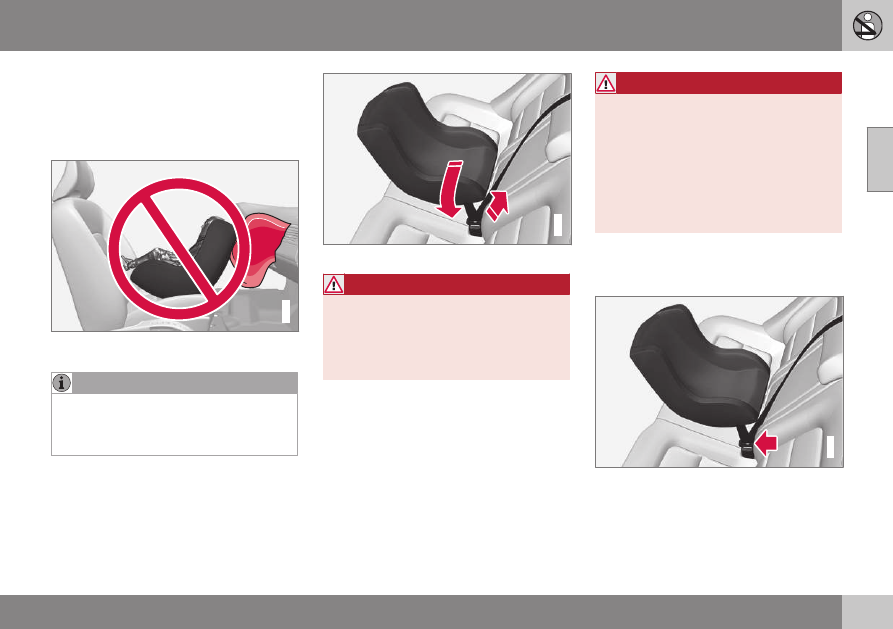
Infant seats
Suitable child restraints should always be
used when children (depending on their age/
size) are seated in the vehicle.
Securing an infant seat with a seat belt
G022844
Do not place the infant seat in the front passeng-
er's seat
Refer to (p. 54) and (p. 55) for infor-
mation on securing a child restraint using
ISOFIX/LATCH lower anchors and/or top
tether anchorages.
1. Place the infant seat in the rear seat of
the vehicle.
2. Attach the seat belt to the infant seat
according to the manufacturer's instruc-
tions.
G023270
Positioning the seat belt through the infant seat
WARNING
•
An infant seat must be in the rear-facing
position only.
•
The infant seat should not be positioned
behind the driver's seat unless there is
adequate space for safe installation.
WARNING
A child seat should never be used in the
front passenger seat of any vehicle with a
front passenger airbag – not even if the
"Passenger airbag off" symbol near the
rear-view mirror is illuminated (on vehicles
equipped with Occupant Weight Sensor). If
the severity of an accident were to cause
the airbag to inflate, this could lead to seri-
ous injury or death to a child seated in this
position.
3. Fasten the seat belt by inserting the latch
plate into the buckle (lock) until a distinct
click is audible.
G023271
Fasten the seat belt