Volvo XC90 T8 Twin Engine Plug-in Hybrid (2017 year). Instruction - part 31
MAINTENANCE AND SERVICING
516
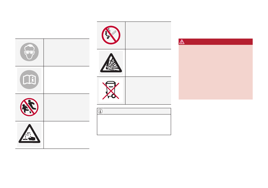
Battery symbols
There are information and warning symbols on
the battery.
Wear protective goggles.
See the owner's manual for
additional information.
Keep batteries away from
children.
Batteries contain corrosive
acid.
Avoid smoking, open
flames, and/or sparks.
Risk of explosion
Recycle properly
A used battery should be disposed of in an
environmentally responsible manner. Consult
your Volvo retailer or take the battery to a
recycling station.
Related information
•
Fuses
The fuses help protect the vehicle's electrical
components from overloading or short circuits.
WARNING
Never use metal objects or fuses with higher
amperage than those stated on the lists of
fuses. Doing so could seriously damage or
overload the vehicle's electrical system.
Orange wires may only be handled by trained
and authorized Volvo service technicians or
licensed electricians.
A number of component in the vehicle used
high voltage electrical current and can be very
dangerous to touch.
Do not touch any components that are not
clearly described in this owner's information.
If an electrical component fails to function, this
may be due to a blown fuse. If the same fuse
blows repeatedly, this indicates a problem with
the component, which should be inspected by a
trained and qualified Volvo service technician.