Volvo Trucks FM Electrical system Manual - part 1


  Index      Volvo     Volvo Trucks FM - Wiring diagram manual


Search                


Content   ..  1  2  3   ..


Volvo Trucks FM Electrical system Manual - part 1


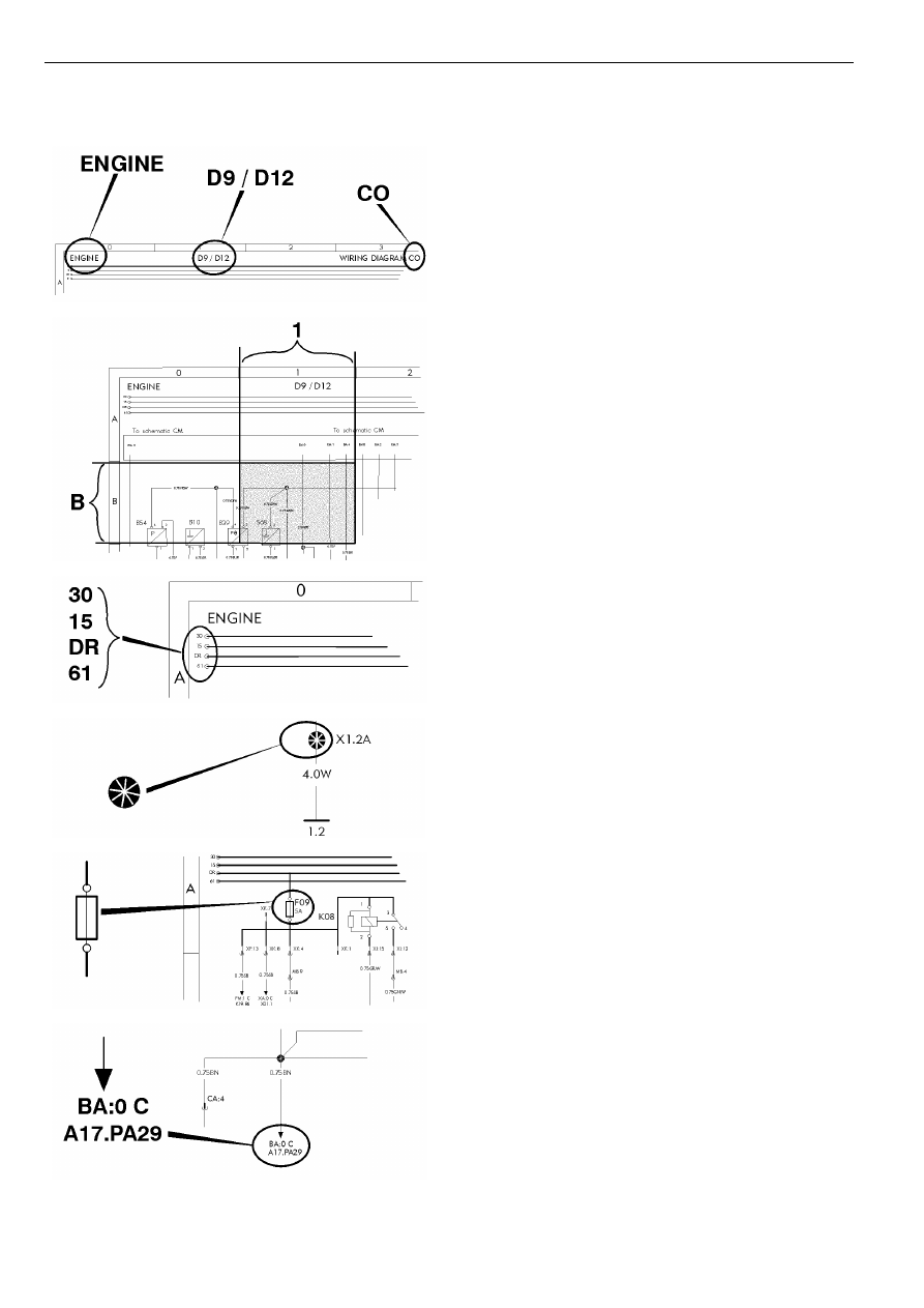
Example of wiring diagram

Component wiring diagram title, variant/subtitle and symbol.

Coordinates (B 1).

30 Voltage battery, kl.30.
15 Voltage with starter key in drive position, kl.15.
DR Voltage with starter key in drive position, preheat
position and start position, kl.DR.
61 Voltage when alternator charges, kl.61.

Splice.

Fuse.

Reference arrow, for diagram BA, coordinates 0 C,
component A17, connector PA pin 29.

2

The maximum of variants are drawn, think about that all
wires and components are not standard for all markets or
vehicle models.

Switch.

Relay.

Conductor on circuit card.

Connector MB terminal 9.

Wire area and colour.

Thin lines, wires.

3

Earth connection point 4, earth connection 1 and wire 2.

Earth connection to circuit card.

Earth connection without wire.

Same splice can be drawn on several diagrams. The wire
from the splice to the earth connection point will only be
drawn and coded on one diagram. On the other diagrams
will only the earth connection point be written besides the
splice.

4

Component wiring diagram index

AA

Power supply, starting system ........................................................................

“”, page 9

AB

Main switch .....................................................................................................

“”, page 10

AC

Power distribution ...........................................................................................

“”, page 11

AE

ADR, main switch ...........................................................................................

“”, page 12

AF

ADR, main switch, ADR3 ................................................................................

“”, page 13

BA

Vehicle ECU ...................................................................................................

“”, page 14

BE

Driver Assistance System, ACC .....................................................................

“”, page 15

BI

Instrument cluster ...........................................................................................

“”, page 16

BM

Tachograph in dash ........................................................................................

“”, page 17

BN

Tachograph in shelf ........................................................................................

“”, page 18

BU

Dynafleet TIS-BAS/TIS-MED/TIS-HIGH .........................................................

“”, page 19

BX

FMS Gateway .................................................................................................

“”, page 20

BZ

Toll collect .......................................................................................................

“”, page 21

BZ RHD

Toll collect .......................................................................................................

“”, page 22

CJ

Engine interface ..............................................................................................

“”, page 23

CO

Engine D11A, D11B, D13A .............................................................................

“”, page 24

Engine D11C, EM-EU5 ...................................................................................

“”, page 25

Engine D11C, EM-EU5 ...................................................................................

“”, page 26

Engine D13B, EGR-C, EM-EC06 ...................................................................

“”, page 27

Engine D13B, EGR-C, EM-EC06 ...................................................................

“”, page 28

Engine D13H, EM-JPN10 ...............................................................................

“”, page 29

Engine D13H, EM-JPN10 ...............................................................................

“”, page 30

Engine D13C, EM-EU5 ...................................................................................

“”, page 31

Engine D13C, EM-EU5 ...................................................................................

“”, page 32

CP

12V trailer ABS converter, VERS-AUS, TABS-12V ........................................

“”, page 33

CR

SCR+DPF, EM-JPN10 ....................................................................................

“”, page 34

CV

SCR ................................................................................................................

“”, page 35

DC

Gear selector ECU (I-SHIFT/POWERTRONIC) .............................................

“”, page 36

DI

Powertronic .....................................................................................................

“”, page 37

DM

Retarder manual gearshift ..............................................................................

“”, page 38

DP

I-shift ...............................................................................................................

“”, page 39

DQ

Power take off .................................................................................................

“”, page 40

DU

Diff-lock ...........................................................................................................

“”, page 41

EE

ABS basic, E-version ......................................................................................

“”, page 42

EE RHD

ABS basic, E-version ......................................................................................

“”, page 43

EF

ABS 6x2 VERS-SAM ......................................................................................

“”, page 44

EO

EBS ECU ........................................................................................................

“”, page 45

EO RHD

EBS ECU ........................................................................................................

“”, page 46

5


Content   ..  1  2  3   ..