Volkswagen 4-cyl. injection engine (1.8 and 2.0 l engine, chain drive). Manual (Edition 08.2018) - page 4
 

  Index      Manuals     Volkswagen 4-cyl. injection engine (1.8 and 2.0 l engine, chain drive). Manual (Edition 08.2018). Workshop Manual (Edition 08.2018)


Search            copyright infringement  


Content      ..     2      3      4      5     ..


Volkswagen 4-cyl. injection engine (1.8 and 2.0 l engine, chain drive). Manual (Edition 08.2018) - page 4


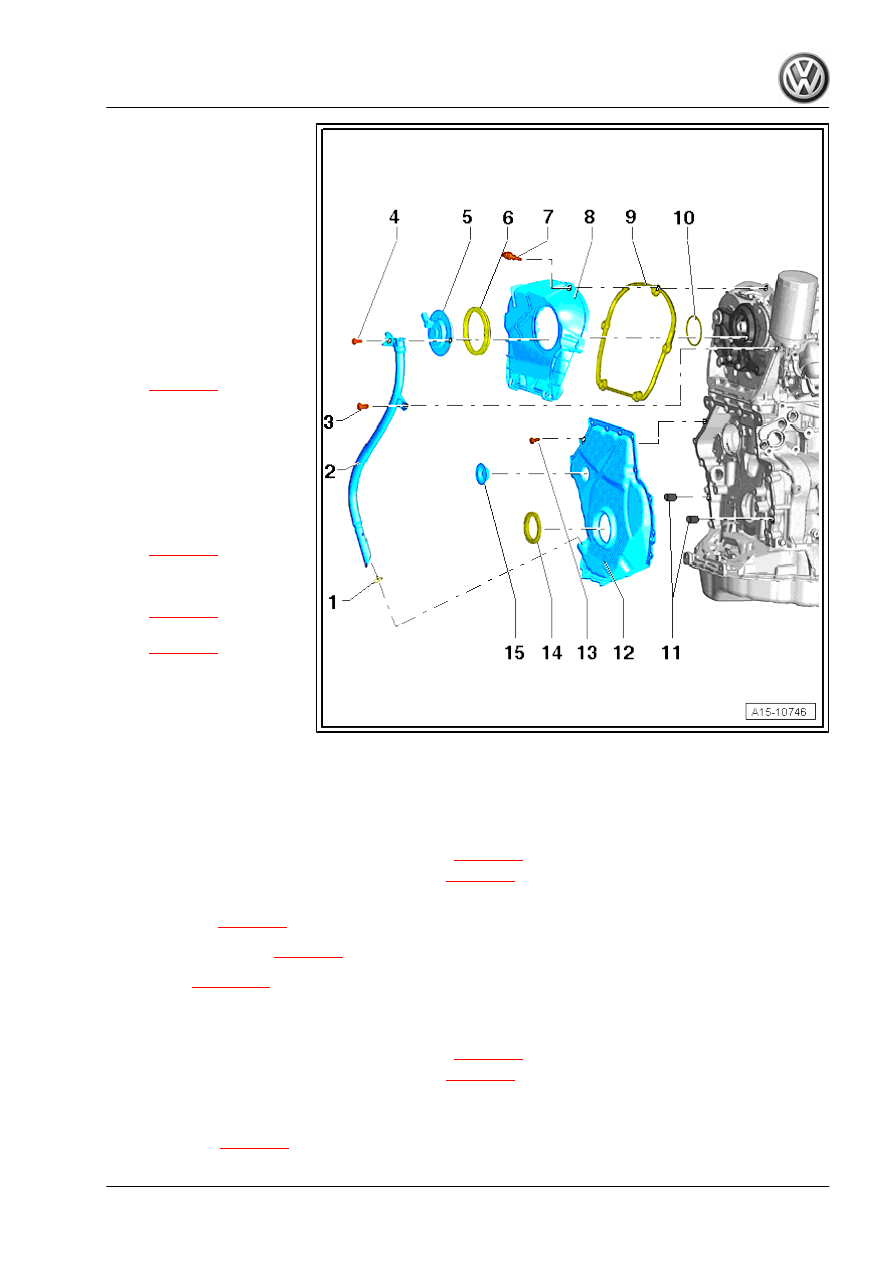
1 - O-ring

❑ Renew
❑ Lubricate before as‐

sembling.

2 - Dipstick guide tube
3 - Bolt

❑ 9 Nm

4 - Bolt

❑ 9 Nm

5 - Inlet camshaft control valve

1 - N205-

❑ Removing and installing

⇒ page 91

6 - Seal

❑ Lubricate before as‐

sembling.

❑ Renew if damaged
❑ To renew, remove cover

7 - Bolt

❑ Tightening sequence

⇒ page 91

8 - Timing chain cover (top)

❑ Removing and installing

⇒ page 91

❑ Tightening sequence

⇒ page 90

9 - Seal

❑ Renew if damaged

10 - O-ring

❑ Renew
❑ Lubricate before assembling.

11 - Dowel pins

❑ For centring cover

12 - Lower timing chain cover

❑ Tightening sequence for version with 15 bolts 

⇒ page 90

❑ Tightening sequence for version with 8 bolts 

⇒ page 90

❑ Removing and installing

Passat CC 

⇒ page 93

Golf, Eos, Scirocco 

⇒ page 99

Tiguan 

⇒ page 106

13 - Bolt

❑ Renew
❑ Tightening sequence for version with 15 bolts 

⇒ page 90

❑ Tightening sequence for version with 8 bolts 

⇒ page 90

14 - Oil seal

❑ For vibration damper
❑ Renewing 

⇒ page 58

89

15 - Plug

❑ Renew

Timing chain cover (top), tightening sequence
– Tighten bolts -1 to 5- in 2 stages in the sequence shown:
1 - Tighten bolts by hand.
2 - Tighten bolts to 9 Nm

Lower timing chain cover - tightening sequence for version with

15 bolts
– Tighten bolts -1 to 15- in 2 stages in the sequence shown:
– 1. Tighten bolts to 8 Nm.
– 2. Turn bolts 45° further.

Lower timing chain cover - tightening sequence for version with 8

bolts
– Tighten bolts -1 to 8- in 2 stages in the sequence shown:
– 1. Tighten bolts to 8 Nm.
– 2. Turn bolts 45° further.

     Rep. gr.15 - Cylinder head, valve gear

1.2

Removing and installing camshaft con‐

trol valve 1 - N205-

– If fitted, remove charge air duct to sound generator

⇒ page 455

 .

– Detach connector from inlet camshaft control valve 1 - N205-

-1-.

– Unscrew bolts -arrows- and remove inlet camshaft control

valve 1 - N205- .

Installing
• Specified torque 

⇒ page 88

Install in reverse order of removal, observing the following.
– Lubricate seal and O-ring with engine oil.

1.3

Removing and installing upper timing

chain cover

Special tools and workshop equipment required
♦ Torque wrench - V.A.G 1783-

♦ Open-end spanner insert AF 10 - V.A.G 1783/1-
Removing
– Remove engine cover panel 

⇒ page 141

 .

– Only vehicles with sound generator: Open catch -1-, unclip fuel

lines -2- and loosen bolt -3- on activated charcoal filter. Place

charge air pipe to one side.

Vehicles with activated charcoal filter in engine compartment:

91

– Pull off breather line -1-, release activated charcoal filter -A-

and remove upwards -B-. Place activated charcoal filter to one

side.

All:

– Unscrew coolant pipe bolts -arrows- from intake manifold.
– Push coolant hoses to one side and secure on engine mount‐

ing using cable ties.

– Removing inlet camshaft control valve 1 - N205- .

– Unscrew bolts -1…5- and remove upper timing chain cover.

Note

Unscrew lower bolts -3- and -5- using an open-end spanner.

Installing:
– Lubricate gasket and O-ring with engine oil.
– Position cover on engine, ensuring that gasket is correctly

seated.

– Hand-tighten bolts -1 to 5- evenly in the sequence shown:
– Further tighten bolts to 9 Nm. Use torque wrench - V.A.G 1783-

and open end spanner insert AF10 - V.A.G 1783/1- for bolts

-3- and -5-.

– Install inlet camshaft control valve 1 - N205- 

⇒ page 91

 .

     Rep. gr.15 - Cylinder head, valve gear

– Tighten bolts -arrows- for guide tube.

Note

If the mounting holes don't align, check if the guide tube has been

inserted to stop into the lower timing chain cover.

• Specified torques 

⇒ page 88

Further assembly is basically a reverse of the dismantling se‐

quence.

1.4

Removing and installing lower timing

chain cover (Passat, CC)

Special tools and workshop equipment required
♦ Locking pin - T10060 A-

♦ Counter-hold tool - T10355-

♦ Assembly tool - T10531-

93

♦ Bits - T10099-

♦ Support - 10 - 222 A-

♦ Passat 2006▶: Rack - 10 - 222 A /1-

♦ CC: Adapter - 10 - 222 A /8-

♦ Silicone sealant ⇒  Electronic parts catalogue (ETKA)
Removing
– Remove vibration damper 

⇒ page 51

 .

– Drain engine oil.
– Support engine in installation position.

     Rep. gr.15 - Cylinder head, valve gear

Passat 2006▶:
♦ Rack - 10 - 222 A /1-
♦ Hook - 10 - 222 A /10-
♦ Shackle - 10 - 222 A /12-

CC:
♦ Adapter - 10 - 222 A /8-
♦ Hook - 10 - 222 A /10-
♦ Shackle - 10 - 222 A /12-

Note

♦

The adapters - 10 - 222 A /8- must not be located on the screw

plates of the wings, as this will otherwise cause damage to

them.

♦

The shackle - 10 - 222 A /12- is needed so the engine is raised

in its installation position and does not »fall back«.

All:
– Take up weight of engine with spindle.

– Unscrew bolts -arrows- of engine/gearbox support on the en‐

gine.

– Removing engine mounting 

⇒ page 21

 .

– Raise engine approx. 50 mm and loosen upper engine support

bolt.

– Now lower engine approx. 100 mm.

– Move electrical wiring harness clear -arrow-.
– Remove bolt -1- and take off tensioning device for poly V-belt

from bracket for ancillaries.

– Unscrew lower bolts for engine support using bits - T10099- .
– Remove engine support with bolts.

95

– Remove bolts -arrows- and pull guide tube for oil dipstick out

of timing chain cover.

– Remove charge pressure solenoid valve - N75- from turbo‐

charger -arrows-.

– Remove turbocharger connection -1-.

– Unscrew bolts -1 … 15-.

Note

Depending on version, the cover may be secured with only 8

bolts.

Caution

Risk of damaging lower timing chain cover. To prevent dam‐

aging the timing chain cover, apply tool only at the bolt holes.

     Rep. gr.15 - Cylinder head, valve gear

– Lever off lower timing chain cover, starting at points

-1 and 2-.

Installing
♦ Specified torques 

⇒ page 88

Note

♦

If the cover was bent during removal, it must be renewed.

♦

Note expiry date of silicone sealant.

♦

The cover must be installed within 5 minutes after applying the

silicone sealant.

♦

Renew bolts which must be tightened further to a torque angle.

♦

Renew seals, gaskets and self-locking nuts.

Caution

♦ Danger of contaminating lubrication system! Cover open

parts of engine.

♦ Wear protective goggles.

– Remove sealant residues from cylinder block with a flat scra‐

per.

– Mask oil seal on both sides with adhesive tape to make sure

seal remains clean.

– Remove remaining sealant from cover, e.g. using rotating

plastic brush.

– Clean sealing surfaces. They must be oil and grease free.
Checking cover for distortion:
– Fit cover using old bolts and tighten to 8 Nm.
– Use feeler gauge to measure distance between cover and

housing (max. distance is 0.2 mm).

Note

♦

Renew cover if distance exceeds 0.2 mm.

♦

It is not possible to measure distance between cover and sump

(top section); check visually to ensure that sealing surface is

even.

97

Installing cover:
– If necessary, unscrew flange nut - T10531/4- , and remove

turning over tool - T10531/3- .

– Check that both dowel pins for centring the cover -arrows- are

fitted.

– Cut off nozzle on tube at front marking (∅ of nozzle approx. 2

mm).

Cover with 15 bolts
– Apply silicone sealant to clean sealing surface -arrow 1- and

to edges -arrows 2- of new cover as shown in illustration.

♦ Thickness of sealant bead: 2 to 3 mm.

     Rep. gr.15 - Cylinder head, valve gear

Cover with 8 bolts
– Apply silicone sealant to clean sealing surface -arrow 1- and

to edges -arrows 2- of new cover as shown in illustration.

♦ Thickness of sealant bead: 2 to 3 mm.

Note

♦

The cover must be installed within 5 minutes after applying the

silicone sealant.

♦

The bead of sealant must not be thicker than specified, other‐

wise excess sealant can enter the sump and obstruct the

strainer in the oil intake pipe.

– Install cover immediately and tighten bolts:
♦ Cover, version with 15 bolts 

⇒ page 90

♦ Cover, version with 8 bolts 

⇒ page 90

– Install vibration damper 

⇒ page 51

 .

Further assembly is basically a reverse of the dismantling se‐

quence.

Note

After fitting cover, let sealant dry for approx. 30 minutes. Only then

fill with engine oil.

– Replenish engine oil and check oil level.

1.5

Removing and installing lower timing chain cover (Golf, Eos, Scirocco)

99

Special tools and workshop

equipment required

♦ Support - 10 - 222 A-
♦ Hook - 10 - 222 A /10-
♦ Shackle - 10 - 222 A /12-
♦ Locking pin - T10060 A-
♦ Bits - T10099-
♦ Golf: frame - 10 - 222 A /13-

♦ Counter-hold tool - T10355-

     Rep. gr.15 - Cylinder head, valve gear

♦ Assembly tool - T10531-

♦ Eos, Scirocco: Rack - 10 - 222 A /1-

Removing
– Remove vibration damper 

⇒ page 51

 .

– Drain engine oil.
Vehicles with sound generator:
– Remove charge air duct to sound generator 

⇒ page 455

 .

All:
– Fit support bracket - 10 - 222 A- with the following tool parts:
Golf:
♦ Adapter - 10 - 222 A /13- , qty. 2
♦ Hook - 10 - 222 A /10-
♦ Shackle - 10 - 222 A /12-

101

Eos, Scirocco:
♦ Rack - 10 - 222 A /1-
♦ Hook - 10 - 222 A /10-
♦ Shackle - 10 - 222 A /12-

Note

♦

The rack feet - 10 - 222 A /1- must not be placed on the bolted

on sheet metal of the wings, or these might be damaged.

♦

The shackle - 10 - 222 A /12- is needed so the engine is raised

in its installation position and does not »fall back«.

All:
– Take up weight of engine with spindle.

– Unscrew bolts -arrows- of engine/gearbox support on the en‐

gine.

– Removing engine mounting 

⇒ page 21

 .

– Raise engine approx. 50 mm and loosen upper engine support

bolt.

– Now lower engine approx. 100 mm.

– Move electrical wiring harness clear -arrow-.
– Remove bolt -1- and take off tensioning device for poly V-belt

from bracket for ancillaries.

– Unscrew lower bolts for engine support using bits - T10099- .
– Remove engine support with bolts.

– Remove bolts -arrows- and pull guide tube for oil dipstick out

of timing chain cover.

     Rep. gr.15 - Cylinder head, valve gear

– Remove charge pressure solenoid valve - N75- from turbo‐

charger -arrows-.

– Remove turbocharger connection -1-.

– Unscrew bolts -1 … 15-.

Note

Depending on version, the cover may be secured with only 8

bolts.

Caution

Risk of damaging lower timing chain cover. To prevent dam‐

aging the timing chain cover, apply tool only at the bolt holes.

103

– Lever off lower timing chain cover, starting at points

-1 and 2-.

Installing:
♦ Specified torques 

⇒ page 88

Note

♦

If the cover was bent during removal, it must be renewed.

♦

Note expiry date of silicone sealant.

♦

The cover must be installed within 5 minutes after applying the

silicone sealant.

♦

Renew bolts which must be tightened further to a torque angle.

♦

Renew seals, gaskets and self-locking nuts.

Caution

♦ Danger of contaminating lubrication system! Cover open

parts of engine.

♦ Wear protective goggles.

– Remove sealant residues from cylinder block with a flat scra‐

per.

– Mask oil seal on both sides with adhesive tape to make sure

seal remains clean.

– Remove remaining sealant from cover, e.g. using rotating

plastic brush.

– Clean sealing surfaces. They must be oil and grease free.
Checking cover for distortion:
– Fit cover using old bolts and tighten to 8 Nm.
– Use feeler gauge to measure distance between cover and

housing (max. distance is 0.2 mm).

Note

♦

Renew cover if distance exceeds 0.2 mm.

♦

It is not possible to measure distance between cover and sump

(top section); check visually to ensure that sealing surface is

even.

     Rep. gr.15 - Cylinder head, valve gear

Installing cover:
– If necessary, unscrew flange nut - T10531/4- , and remove

turning over tool - T10531/3- .

– Check that both dowel pins for centring the cover -arrows- are

fitted.

– Cut off nozzle on tube at front marking (∅ of nozzle approx. 2

mm).

Cover with 15 bolts
– Apply silicone sealant to clean sealing surface -arrow 1- and

to edges -arrows 2- of new cover as shown in illustration.

♦ Thickness of sealant bead: 2 to 3 mm.

105

Cover with 8 bolts
– Apply silicone sealant to clean sealing surface -arrow 1- and

to edges -arrows 2- of new cover as shown in illustration.

♦ Thickness of sealant bead: 2 to 3 mm.

Note

♦

The cover must be installed within 5 minutes after applying the

silicone sealant.

♦

The bead of sealant must not be thicker than specified, other‐

wise excess sealant can enter the sump and obstruct the

strainer in the oil intake pipe.

– Install cover immediately and tighten bolts:
♦ Cover, version with 15 bolts 

⇒ page 90

♦ Cover, version with 8 bolts 

⇒ page 90

– Install vibration damper 

⇒ page 51

 .

Further assembly is basically a reverse of the dismantling se‐

quence.

Note

After fitting cover, let sealant dry for approx. 30 minutes. Only then

fill with engine oil.

– Replenish engine oil and check oil level.

1.6

Removing and installing bottom timing

chain cover (Tiguan)

Special tools and workshop equipment required
♦ Support - 10-222A-

♦ Shackle - 10-222A/12-
♦ Adapter - 10-222A/16-
♦ Adapter - 10-222A/18-
♦ Adapter - 10-222A/22-
♦ Adapter - 10-222A/19-

     Rep. gr.15 - Cylinder head, valve gear

♦ Square tube - T40091/1-

♦ Swivel joint - T40091/3-

♦ Locking pin - T10060 A-

♦ Counter-hold tool - T10355-

♦ Assembly tool - T10531-

107

♦ Bits - T10099-

♦ Silicone sealant ⇒  Electronic parts catalogue (ETKA)
Removing
– Remove vibration damper 

⇒ page 51

 .

– Drain engine oil.
– Remove engine cover panel 

⇒ page 141

 .

– Fit support bracket - 10 - 222 A- as shown. The rear spindle is

not required. Attach hooks to support eyes on engine and

support engine and gearbox.

– Take up weight of engine with spindle.

– Unscrew bolts -arrows- of engine/gearbox support on the en‐

gine.

– Removing engine mounting 

⇒ page 23

 .

– Raise engine approx. 50 mm and loosen upper engine support

bolt.

– Now lower engine approx. 100 mm.

     Rep. gr.15 - Cylinder head, valve gear

– Move electrical wiring harness clear -arrow-.
– Remove bolt -1- and take off tensioning device for poly V-belt

from bracket for ancillaries.

– Unscrew lower bolts for engine support using bit - T10099- .
– Remove engine support with bolts.

– Remove bolts -arrows- and pull guide tube for oil dipstick out

of timing chain cover.

– Remove charge pressure solenoid valve - N75- from turbo‐

charger -arrows-.

– Remove turbocharger connection -1-.

– Unscrew bolts -1 … 15-.

Note

Depending on version, the cover may be secured with only 8

bolts.

Caution

Risk of damaging lower timing chain cover. To prevent dam‐

aging the timing chain cover, apply tool only at the bolt holes.

109

– Lever off lower timing chain cover, starting at points

-1 and 2-.

Installing:
♦ Specified torques 

⇒ page 88

Note

♦

If the cover was bent during removal, it must be renewed.

♦

Note expiry date of silicone sealant.

♦

The cover must be installed within 5 minutes after applying the

silicone sealant.

♦

Renew bolts which must be tightened further to a torque angle.

♦

Renew seals, gaskets and self-locking nuts.

Caution

♦ Danger of contaminating lubrication system! Cover open

parts of engine.

♦ Wear protective goggles.

– Remove sealant residues from cylinder block with a flat scra‐

per.

– Mask oil seal on both sides with adhesive tape to make sure

seal remains clean.

– Remove remaining sealant from cover, e.g. using rotating

plastic brush.

– Clean sealing surfaces. They must be oil and grease free.
Checking cover for distortion:
– Fit cover using old bolts and tighten to 8 Nm.
– Use feeler gauge to measure distance between cover and

housing (max. distance is 0.2 mm).

Note

♦

Renew cover if distance exceeds 0.2 mm.

♦

It is not possible to measure distance between cover and sump

(top section); check visually to ensure that sealing surface is

even.

     Rep. gr.15 - Cylinder head, valve gear

Installing cover:
– If necessary, unscrew flange nut - T10531/4- , and remove

turning over tool - T10531/3- .

– Check that both dowel pins for centring the cover -arrows- are

fitted.

– Cut off nozzle on tube at front marking (∅ of nozzle approx. 2

mm).

Cover with 15 bolts
– Apply silicone sealant to clean sealing surface -arrow 1- and

to edges -arrows 2- of new cover as shown in illustration.

♦ Thickness of sealant bead: 2 to 3 mm.

111

Cover with 8 bolts
– Apply silicone sealant to clean sealing surface -arrow 1- and

to edges -arrows 2- of new cover as shown in illustration.

♦ Thickness of sealant bead: 2 to 3 mm.

Note

♦

The cover must be installed within 5 minutes after applying the

silicone sealant.

♦

The bead of sealant must not be thicker than specified, other‐

wise excess sealant can enter the sump and obstruct the

strainer in the oil intake pipe.

– Install cover immediately and tighten bolts:
♦ Cover, version with 15 bolts 

⇒ page 90

♦ Cover, version with 8 bolts 

⇒ page 90

– Install vibration damper 

⇒ page 51

 .

Further assembly is basically a reverse of the dismantling se‐

quence.

Note

After fitting cover, let sealant dry for approx. 30 minutes. Only then

fill with engine oil.

– Replenish engine oil and check oil level.

1.7

Camshaft timing chain - exploded view

     Rep. gr.15 - Cylinder head, valve gear

1 - Bolt

❑ 9 Nm

2 - Chain tensioner

❑ Is spring-loaded
❑ Depending on version,

secure with locking pin -

T40011- or locking tool -

T40267- .

3 - Tensioning rail for timing

chain
4 - Guide pin

❑ 20 Nm

5 - Bolt

❑ 9 Nm

6 - Timing valve

❑ Left-hand thread
❑ Checking 

⇒ page 114

❑ Remove with assembly

tool - T10352-

❑ Engine codes CCZA,

CCZB, CCZC, CCZD,

CDAA, CDAB: use as‐

sembly tool - T10352/1-

to remove

❑ 35 Nm

7 - Bolt

❑ Renew
❑ M6: 8 Nm + 90° further
❑ M8: 20 Nm + 90° further

8 - Washer
9 - Bearing saddle
10 - Guide rail for camshaft timing chain
11 - Camshaft case
12 - Camshaft timing chain

❑ Before removing, mark running direction with paint
❑ Removing and installing 

⇒ page 114

13 - Guide rail for camshaft timing chain
14 - Guide pin

❑ 20 Nm

15 - Sprocket

❑ Crankshaft
❑ Fitting position 

⇒ page 114

113

Checking control valve
– It must be possible to press in piston -1- approx. 3 mm against

spring force. It must move freely, without sticking.

Crankshaft chain sprocket - installation position
• The two sections -arrows- must be aligned.

1.8

Removing and installing camshaft timing chain

     Rep. gr.15 - Cylinder head, valve gear

Special tools and workshop

equipment required

♦ Assembly tool - T10352-
♦ Engine codes CCZA, CCZB, CCZC, CCZD, CDAA, CDAB:

assembly tool - T10352/1-

♦ Counter-hold tool - T10355-
♦ Pin - T40011-
♦ Assembly lever - T40243-
♦ Locking tool - T40267-
♦ Camshaft clamp - T40271-

115

♦ Assembly tool - T10531-

Components of assembly tool - T10531- :
♦ Support - T10531/1-
♦ Clamping pin - T10531/2-
♦ Turning over tool - T10531/3-
♦ Flange nut - T10531/4-
Removing:
– Remove timing chain cover (top) 

⇒ page 91

 .

– Turn vibration damper to “TDC” position -arrow- using coun‐

terhold - T10355- .

• Notch on vibration damper must align with arrow marking on

cover for timing chains (bottom).

• The markings -1- on the camshafts must face upwards.
– Remove vibration damper 

⇒ page 51

 .

– Remove lower timing chain cover:

Passat CC 

⇒ page 93

Golf, Eos, Scirocco 

⇒ page 99

Tiguan 

⇒ page 106

– Remove control valve using assembly tool - T10352- (engine

codes CCZA, CCZB, CDAA, CDAB: assembly tool -

T10352/1- ) in -direction of arrow-.

Caution

The control valve has a left-hand thread.

     Rep. gr.15 - Cylinder head, valve gear

– Remove bolts -arrows- and detach bearing saddle.

– Press oil pump chain tensioner in direction of -arrow- and lock

in place using locking pin - T40011- .

– Remove chain tensioner for drive chain -1-.

– Unscrew bolts -arrows-.

Depending on version, either of 2 different chain tensioners may

be installed. Variant 1:
– Screw in lever - T40243- -arrows-.
– Raise locking element of chain tensioner -arrow 1-. To do this,

grind the tip of the locking pin - T40011- to a point. A screw‐

driver with a blade width of approx. 1.5 mm can also be used.

Caution

Avoid damage to chain tensioner! Proceed with great care.

– Slowly push valve lever - T40243- in -direction of arrow 2- and

hold it in that position.

117

– Secure chain tensioner with locking pin - T40011- .

Version 2:
– Screw in lever - T40243- -arrows-.
– Press together retaining ring -1- of chain tensioner and hold it

in that position.

– Slowly push lever - T40243- in -direction of arrow-, and hold it

in that position.

– Secure chain tensioner with locking pin - T40267- .
All
– Remove lever - T40243- .

     Rep. gr.15 - Cylinder head, valve gear

– Bolt camshaft clamp - T40271/2- to cylinder head and insert it

in direction of arrow -2- between teeth of sprocket. If necessary

turn inlet camshaft slightly using spanner -1-.

– Bolt camshaft clamp - T40271/1- to cylinder head. Brace cam‐

shaft clockwise -arrow- using open-end spanner.

– Unscrew bolt -A- and remove tensioning rail while continuing

to brace camshaft.

– Insert camshaft clamp - T40271/1- between teeth of sprocket

-2-. If necessary, turn exhaust camshaft clockwise -1- until the

camshaft clamp can be inserted. The camshaft timing chain

between the sprockets must be »loose«.

119

– Unscrew bolts -A- and remove guide rail for camshaft timing

chain.

– Remove camshaft timing chain from camshaft sprockets and

fit it onto camshaft journals -arrows-.

– Remove chain tensioner -1- for balance shaft drive chain.

– Unscrew bolts -1-. Remove tensioning rail -2- and guide rails

-3- and -4-.

     Rep. gr.15 - Cylinder head, valve gear


Content      ..     2      3      4      5     ..