Volkswagen Golf / Golf GTI / Golf Variant. Manual - part 955


  Index      Volkswagen     Volkswagen Golf / Golf GTI / Golf Variant - service repair manual 2013 year


Search            copyright infringement  


Content   ..  953  954  955  956   ..


Volkswagen Golf / Golf GTI / Golf Variant. Manual - part 955


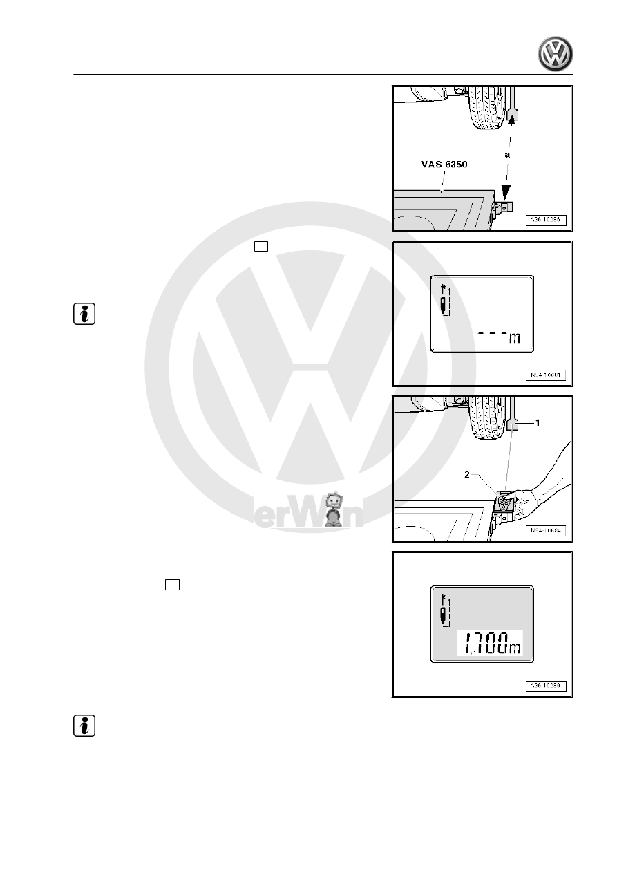
– Position the -VAS6350A- at distance -a- to the rear wheels.
• Dimension -a- = 1700 ± 2 mm

– Switch on the -VAS6350/2- with the 

ON

 button.

Display on the -VAS6350/2- :
• “- - - m”

Note

The laser is switched on at same time.

– Hold the -VAS6350/2- -2- flush against the catch bracket, as

shown in the illustration, for the distance measurement.

• The -VAS6350/2- must lie firmly against the catch bracket.
– Make sure the “laser beam” for the distance measurement

contacts the paddle on lower enlarged part -1-.

If that is not the case, correct the measuring paddle height using

the locking nuts on the -VAS6350/1- .
– Briefly press the 

ON

 button for distance measurement.

Display on the -VAS6350/2- :
• “1,700 m” (specified value: 1700 ± 2 mm).
– Repeat the measurement procedure from the left catch brack‐

et to measuring paddle on left rear wheel.

• The distance value must be the same on both sides.
If both measured values are not the same, adjust the -VAS6350A-

accordingly.

Note

The vehicle in the illustration is only a basic outline.

– Secure the Calibration Tool - Lane Change Calibration Tool -

VAS6350/4- to the Calibration Unit - VAS6350A- mount on the

rear left side.

• When installed correctly, the vehicle electrical system voltage

line must be connected at bottom left of calibration device (as

seen in direction of travel).

• Sedan dimension -a- = 606 mm (measured from the upper

edge of the calibration device to workshop floor).

• Wagon dimension -a- = 618 mm (measured from the upper

edge of the calibration device to workshop floor).

– The adjustment dimension is set with the measuring point

-arrow- on the base of the calibration device on the scale of

the steel ruler -1-.

• Left adjustment dimension for Sedan = 621 mm (read on

measuring scale -1-).

• Left adjustment dimension for Wagon = 678 mm (read on

measuring scale -1-).

– Connect the Calibration Tool - Lane Change Calibration Tool

Calibration Tool - Lane Change Calibration Tool - VAS6350/4-

to the vehicle electrical system voltage.

– Using the bubble level (level indicator) -arrow-, bring the Cal‐

ibration Unit - VAS6350A- into a horizontal position by turning

the plastic bases.

– Wear laser protective eyewear.

Note

The vehicle in the illustration is only a basic outline.

– Turn on the Calibration Laser - VAS6350/3A- on the Calibra‐

tion Unit - VAS6350A- .

– Align the entire Calibration Unit - VAS6350A- so that the laser

beam shines on the center of the vehicle rear above the VW

logo.

– Check right and left distance between catch bracket on the

Calibration Unit - VAS6350A- and measuring paddle -1- on

wheel mountings again.

• Specified value: 1700 ± 2 mm
Blind Spot Detection Control Module, Calibrating. Refer to

⇒ “13.4.3  Blind Spot Detection Control Module J1086 / Blind Spot

Detection Control Module 2 J1087 , Calibrating”, page 227

 .

13.4.3

Blind Spot Detection Control Module -

J1086- / Blind Spot Detection Control

Module 2 - J1087- , Calibrating

Special tools and workshop equipment required
♦ Calibration Unit - VAS6350A-
♦ Vehicle Diagnostic Tester

Note

Before the actual calibration procedure for the control modules,

the Calibration Unit - VAS6350A- must be set up as described in

the chapter.

The following should not occur during the calibration procedure:
• Vehicle doors must not be opened or closed.
• People must not sit in the vehicle.
• People must not go between the vehicle and the Calibration

Tool - Lane Change Calibration Tool - VAS6350/4- .

Procedure:
– Turn on the Calibration Tool - Lane Change Calibration Tool -

VAS6350/4- at the power switch -3-.

• The green LED -1- must turn on.

Note

If the red LED -2- lights up: Check the Calibration Tool - Lane

Change Calibration Tool Calibration Tool - Lane Change Calibra‐

tion Tool - VAS6350/4- .

– Connect the Vehicle Diagnostic Tester .
– Select calibration.
– Follow the instructions in the Vehicle Diagnostic Tester dis‐

play.

Note

The vehicle in the illustration is only a basic outline.

During the program sequence, there is a prompt to switch the

Calibration Tool - Lane Change Calibration Tool - VAS6350/4-

from the left to the right side of the Calibration Tool - VAS6350- .
– Turn off the Calibration Tool - Lane Change Calibration Tool -

VAS6350/4- and remove the calibration tool.

• When installed correctly, the vehicle electrical system voltage

line must be connected at bottom left of calibration device (as

seen in direction of travel).

• Sedan dimension -a- = 606 mm (measured from the upper

edge of the calibration device to workshop floor).

• Wagon dimension -a- = 618 mm (measured from the upper

edge of the calibration device to workshop floor).

• Right adjustment dimension for Sedan = 621 mm (read on

measuring scale -1-).

• Right adjustment dimension for Wagon = 678 mm (read on

measuring scale -1-).

– Turn on the -VAS6350/4- at the power switch -3-.
• The green LED -1- must turn on.
– Follow the instructions in the Vehicle Diagnostic Tester dis‐

play.

After a successful blind spot detection calibration, switch off the

ignition and disconnect the diagnostic connector.


Content   ..  953  954  955  956   ..