Volkswagen Golf / Golf GTI / Golf Variant. Manual - part 940


  Index      Volkswagen     Volkswagen Golf / Golf GTI / Golf Variant - service repair manual 2013 year


Search            copyright infringement  


Content   ..  938  939  940  941   ..


Volkswagen Golf / Golf GTI / Golf Variant. Manual - part 940


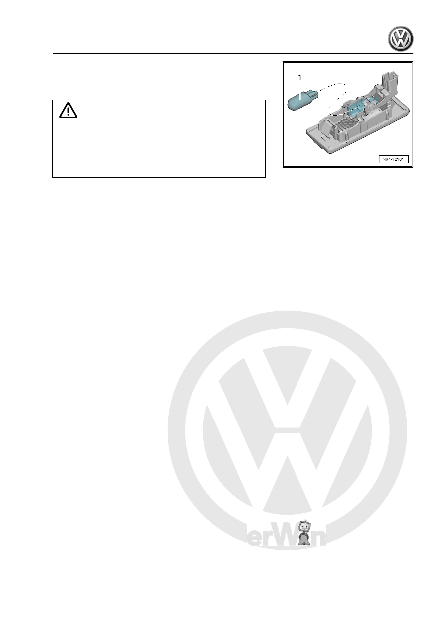
– Remove the glass base bulb -1- from the bulb socket.
Installing
Install in reverse order of removal. Note the following:

Caution

There is a risk of damaging the lamp.

♦ Do not touch glass cone of bulb with bare fingers. Fingers

will leave traces of grease on the glass which, when the

bulb is switched on, will evaporate and cloud the glass.

♦ Use clean gloves for example to insert the bulbs.

– Perform a function test.

1 - Anti-Theft Immobilizer

Reader Coil - D2-

❑ Removing and instal‐

ling. Refer to

⇒ “8.10.2  Anti-Theft Im‐

mobilizer Reader Coil

D2 , Removing and In‐

stalling, Vehicles with

Keyless Access”,

page 194

 .

2 - Electronic Steering Column

Lock Control Module - J764-

❑ Removing and instal‐

ling. Refer to ⇒  Suspen‐

sion, Wheels, Steering;

Rep. Gr.  48 ; Steering

Column; Electronic

Steering Column Lock

Control Module - J764- ,

Removing and Installing

3 - Start System Button - E378-

❑ Removing and instal‐

ling. Refer to

⇒ “2.26  Start System

Button E378 , Removing

and Installing”,

page 273

 .

4 - Vehicle Electrical System

Control Module - J519-

❑ With Central Locking

and Anti-Theft Alarm

System Antenna - R47-

❑ Overview. Refer to

⇒ “2.2 Overview - Con‐

trol Modules”,

page 298

 .

5 - Access/Start System Inter‐

face - J965-

❑ Removing and installing. Refer to

⇒ “7.3  Access/Start System Interface J965 , Removing and Installing”, page 170

 .

❑ Bracket screws (only for NAR): 2 Nm

7.2

Component Location Overview - Key‐

less Access Authorization System

⇒ “7.2.1 Component Location Overview - Front Keyless Access

Component Location Overview - Front Keyless Access Authorization Sys‐

tem

Note

The component locations for the Sedan are shown. The component locations for the Wagon are identical.

1 - Front Passenger Exterior

Door Handle

❑ With Front Passenger

Exterior Door Handle

Touch Sensor - G416-

removing and installing.

Refer to

⇒ “7.4 Driver Exterior

and Front Passenger

Exterior Door Handle

Touch Sensor G415 /

G416 , Removing and

Installing”, page 172

 .

❑ With Front Passenger

Access/Start System

Antenna - R135- , re‐

moving and installing.

Refer to

⇒ “7.7  Front Passenger

Access/Start System

Antenna R135 , Remov‐

ing and Installing ”, page

173

 .

2 - Access/Start System An‐

tenna 1 in Vehicle Interior -

R138-

❑ Removing and instal‐

ling. Refer to

⇒ “7.5  Access/Start

System Antenna 1 in

Vehicle Interior R138 ,

Removing and Instal‐

ling”, page 173

 .

3 - Driver Side Exterior Door

Handle

❑ With Driver Exterior

Door Handle Touch

Sensor - G415- remov‐

ing and installing. Refer to

⇒ “7.4 Driver Exterior and Front Passenger Exterior Door Handle Touch Sensor G415 / G416 , Removing

and Installing”, page 172

 .

❑ With Driver Access/Start System Antenna - R134- , removing and installing. Refer to

⇒ “7.6  Driver Access/Start System Antenna R134 , Removing and Installing”, page 173

 .


Content   ..  938  939  940  941   ..