Volkswagen Golf / Golf GTI / Golf Variant. Manual - part 882


  Index      Volkswagen     Volkswagen Golf / Golf GTI / Golf Variant - service repair manual 2013 year


Search            copyright infringement  


Content   ..  880  881  882  883   ..


Volkswagen Golf / Golf GTI / Golf Variant. Manual - part 882


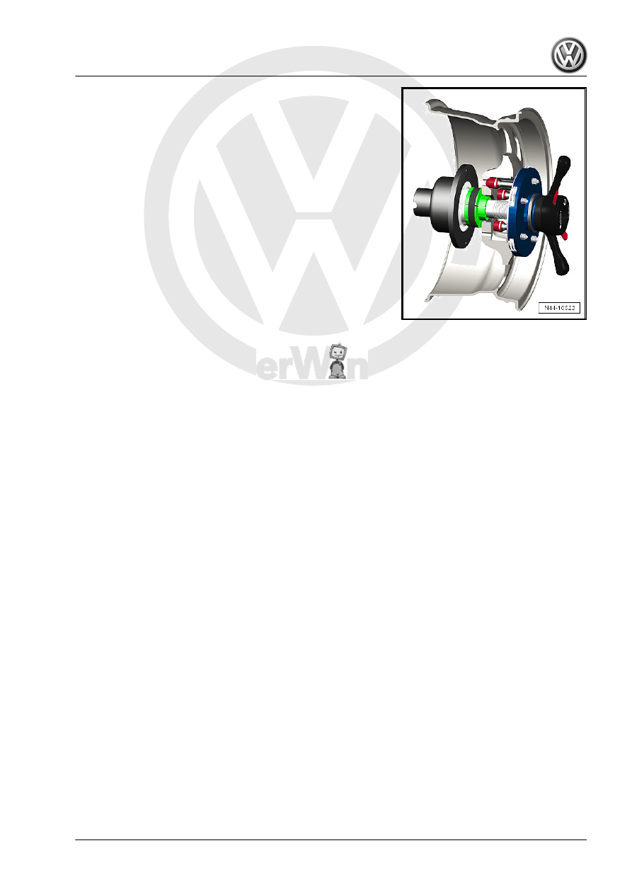
– Tension the wheel with the tire on the balancing machine.

Note

To mount wheel on wheel balancer, use for example Wheel

Centering System Adapter - VAS5271- .

This way a 100% centering of the wheel and gentle mounting

is possible!

It is not possible to center it 100% on balancing machine with

conical tensioners.

With a deviation of 0.1 mm outside the center, there is an im‐

balance of 10 grams on the wheel/tire.

Wheel/Tire Balancing Procedure
– Let the wheel/tire turn on the balancing machine.
– Check the run of the characteristic lines on the sidewall of the

tire in the area of the rim flange.

– Check the tire wear pattern while the wheel/tire is turning.

Note

In the event of one-sided wear, flat spots from braking or severe

wear spots, smooth running cannot be achieved by balancing. In

this case, the tire must be replaced.

– Check the run-out on the wheel/tire. If the wheel with tire runs

untrue although there are no flat spots, a radial or lateral run-

out may be the cause.

– Check wheel with tire for radial- and lateral run-out. Refer to

⇒ “4.5.2 Wheels and Tires, Radial and Lateral Run Out,

Checking with Tire Dial Gauge”, page 317

 .

– If the radial and lateral run-out are within the specified toler‐

ance, balance the wheel and tire.

Note

Do not use more than 60 grams of weight per wheel.

If more weight is necessary, a smoother running can achieved

by matched mounting of the tire. Tires matching. Refer to

⇒ “4.7 Wheels and Tires, Matching”, page 318

 .

The display in the balancing machine should show 0 grams.

Hunter RFT33VAG Road Force Touch™ Wheel Balancer -

VAS6230B4- can be inserted as an alternative to matching.

Refer to 

⇒ “4.4 Vibration Control System”, page 316

 .

– Install the wheel on the vehicle.
– First, tighten the lowest wheel bolt hand-tight to approximately

30 Nm.

– Tighten the remaining wheel bolts diagonally to approximately

30 Nm. This process centers the wheel on the wheel hub.

– Lower vehicle onto its wheels.
– Now use a torque wrench to tighten the wheel bolts diagonally

to the specified tightening specification.

Road Test, Performing
– Perform a road test after balancing the wheel/tires.
If a vibration is still detected during the road test, the cause may

be due to tolerance in the wheel centering.
The component tolerances of wheels and wheel hubs can be ad‐

ditive in unfavorable cases. Vibration can result from this. This

can be eliminated using a finish balancer. Refer to

⇒ “4.3.3 Wheel, Balancing with Finish Balancer”, page 315

 .

4.3.3

Wheel, Balancing with Finish Balancer

Note

Working with a Finish Balancer requires instruction from the

manufacturer of the balancer.

When balancing, place the wheels of the driven axle on the

turntable sensors. On a FWD vehicle, the front wheels must

be on the sensors. On AWD vehicles, all four wheels must be

on the sensors.

If it is determined when balancing on the vehicle the remaining

imbalance is more than 20 grams, the wheel should be rotated on

the wheel hub.
– Mark the point at which the imbalance is indicated.
– Afterwards, unbolt the wheel and rotate its position on the

wheel hub so that the marking points downward.

Note

The wheel hub must not turn during this procedure.

– First, tighten the lowest wheel bolt hand-tight to approximately

30 Nm.

– Tighten the remaining wheel bolts diagonally to approximately

30 Nm. This process centers the wheel properly on the wheel

hub.

– Check again whether the imbalance is less than 20 grams us‐

ing the finish balancer.

Note

The imbalance should not be smaller than 20 grams under any

circumstances before changing balance weight.

– Loosen the wheel bolts again, if necessary.
– Rotate the wheel relative to the wheel hub once more by one

or two wheel bolt holes.

– Tighten the wheels according to the method described above.

Note

Only if the imbalance is less than 20 grams should the imbalance

be reduced by changing the balance weight.

– Balance the wheels until the imbalance is below 5 grams.
– Tighten the wheel bolts to the specified tightening specification

if you have not already done so.

WARNING

Always tighten the wheel bolt to the tightening specification and

using the torque wrench.

4.4

Vibration Control System

Expanded functions can be performed using Hunter RFT33VAG

Road Force Touch™ Wheel Balancer - VAS6230B4- in addition

to the previously known balancers.
A special characteristic of this system is testing the radial force of

wheel/tire during rolling.
For this purpose, a roller presses a force of approximately 635 kg

(1400 lbs) against the wheel. This simulates the tire contact force

against the street surface while driving.
Tire contact forces fluctuate due to radial- and lateral run-out and

differing rigidity in the tires.
The Hunter RFT33VAG Road Force Touch™ Wheel Balancer -

VAS6230B4- detects and stores the position of the maximum

measured radial force in the tires. After that, the position of small‐

est dimension between rim flange and disc wheel center is meas‐

ured.

4.5

Tire and Wheel Radial and Lateral Run-

Out, Checking

⇒ “4.5.1 Tire and Wheel Radial and Lateral Run-Out, Checking,

Tolerances”, page 316
⇒ “4.5.2 Wheels and Tires, Radial and Lateral Run Out, Checking

with Tire Dial Gauge”, page 317

4.5.1

Tire and Wheel Radial and Lateral Run-

Out, Checking, Tolerances

Radial and lateral run-out occur when the wheel and tire are not

running precisely true.
For technical reasons, 100% true running is not possible.
Therefore the manufacturers of these components allow a pre‐

cisely specified tolerance.
Mounting the tire in a unfavorable position on the wheel can be

the cause for exceeding the maximum allowed tolerance for

wheel with tire.
The table shows the maximum permissible tolerance values for

the wheel with mounted tire.
Tolerances for Radial and Lateral Run-Out of Rim with Tire

Rim with Tire

Radial Run-Out (mm)

Lateral Run-Out (mm)

Passenger vehicle

0.9

1.1

(1.3 near the lettering)


Content   ..  880  881  882  883   ..