Volkswagen Golf / Golf GTI / Golf Variant. Manual - part 863


  Index      Volkswagen     Volkswagen Golf / Golf GTI / Golf Variant - service repair manual 2013 year


Search            copyright infringement  


Content   ..  861  862  863  864   ..


Volkswagen Golf / Golf GTI / Golf Variant. Manual - part 863


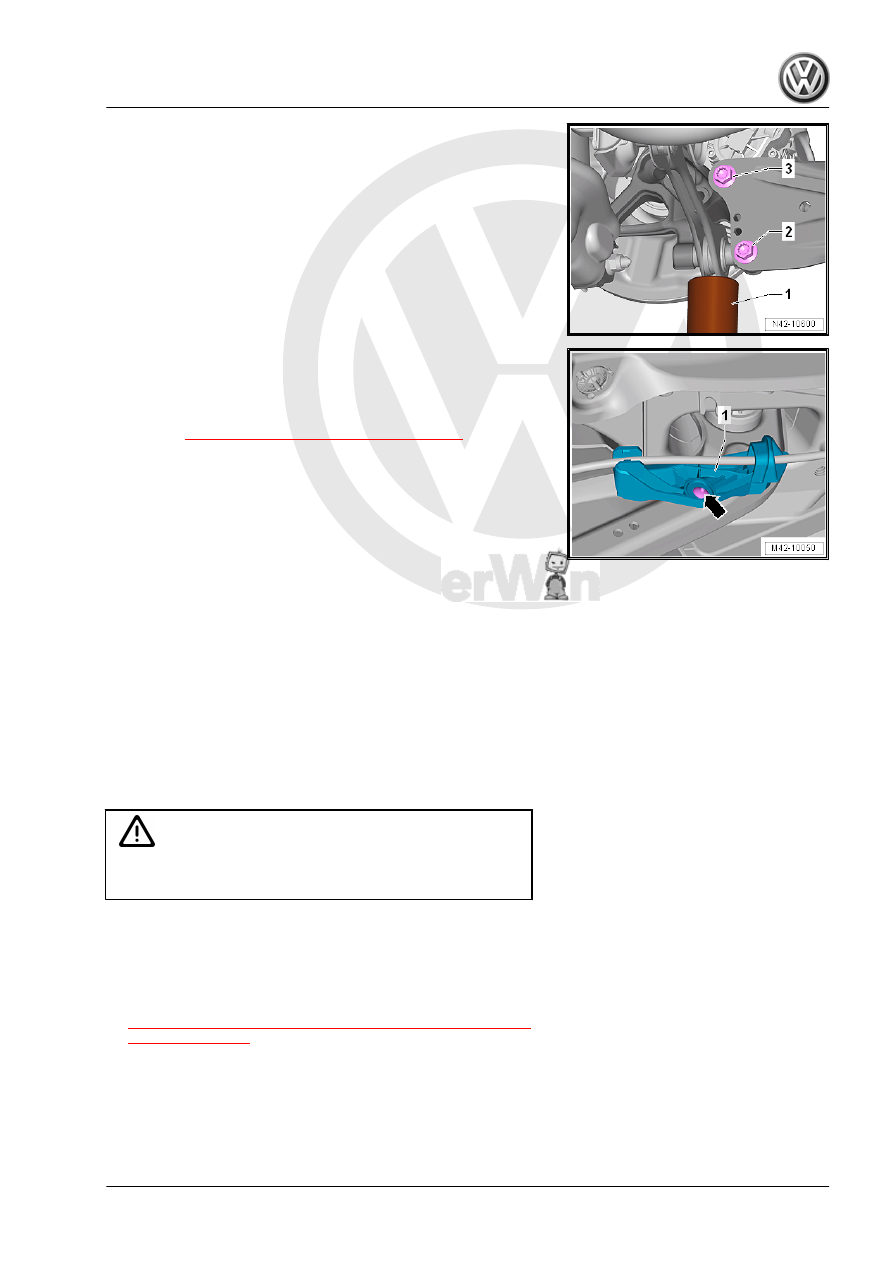
– Tighten the bolts -2 and 3-.

– Position the bracket -1- on the trailing arm.
– Insert a new rivet and push in a new inner pin -arrow-.
Tightening Specifications
♦ Refer to 

⇒ “7.2 Overview - Trailing Arm”, page 213

After Installation, the Axle Alignment Must Be Checked on an

Alignment Rack.

7.7

Trailing Arm, Servicing

Special tools and workshop equipment required
♦ Bearing Installer - Wheel Bearing - 3345-
♦ Bearing Installer - Control Arm - 3346-
♦ Press Plate - VW402-
♦ Press Piece - Multiple Use - VW412-
♦ Press Piece - Trailing Arm Bushing - T10496-
♦ Torque Wrench 1332 40-200Nm - VAG1332-
♦ Engine and Gearbox Jack - VAS6931-

Caution

This procedure contains mandatory replaceable parts. Refer

to component overview prior to starting procedure.

Mandatory Replacement Parts
♦ Bolts - Trailing Arm to Wheel Bearing Housing
♦ Bolt - Trailing Arm to Mounting Bracket
– Remove trailing arm with mounting bracket. Refer to

⇒ “7.6 Trailing Arm with Mounting Bracket, Removing and In‐

stalling”, page 234

 .

– Clamp the trailing arm -1- in the vise with protective covers.
– Remove the bolt -2- and remove the mounting bracket -3- from

the trailing arm.

Pressing Out the Bonded Rubber Bushing
– Mount the tools as illustrated.
1 - Press Piece - Multiple Use - VW412-
2 - Bearing Installer - 3346/1- from the Bearing Installer - Con‐

trol Arm - 3346- (the deep recess points to the bonded

rubber bushing)

3 - Trailing arm
4 - Bonded rubber bushing
5 - Bearing Installer - Wheel Bearing - 3345-
6 - Press Plate - VW402-
– Press out the bonded rubber mount.

Installing the Bonded Rubber Bushing
– Mark the position of the bonded rubber bushing on the trailing

arm with a right angle.

– Place the outer edge of the right angle on the upper -1- and

lower radius -2- of the hole.

– Make a mark over and under the bushing on the trailing arm

-arrows-.

a - 90°

Position the bonded rubber bushing on the trailing arm so that the

marked line -arrows- runs along the ribs -1-.

Note

Make absolutely sure that the bonded rubber bushing is in the

correct installation position in relation to the trailing arm socket.

– Mount the tools as illustrated.
1 - Press Piece - Multiple Use - VW412-
2 - Press Piece - Trailing Arm Bushing - T10496-
3 - Bonded rubber bushing
4 - Trailing arm
5 - Bearing Installer - Wheel Bearing - 3345-
6 - Press Plate - VW402-
– Install the bonded rubber bushing.
Determining Installation Position of Mounting Bracket Relative to

Trailing Arm

– Clamp the trailing arm -2- in the vise with jaw protectors.
– Position the mounting bracket -1- on the trailing arm -2-.
– Install the bolt -3-.
– Adjust the dimension -a- to 37 mm and tighten the bolt -3-.
– Install the trailing arm with mounting bracket. Refer to

⇒ “7.6 Trailing Arm with Mounting Bracket, Removing and In‐

stalling”, page 234

 .

8

Drive Axle

⇒ “8.1 Overview - Drive Axle”, page 240
⇒ “8.2 Drive Axle Threaded Connection, Loosening and Tighten‐

ing”, page 241
⇒ “8.3 Drive Axle, Removing and Installing”, page 242
⇒ “8.4 Drive Axle, Disassembling and Assembling”, page 247
⇒ “8.5 Outer CV Joint, Checking”, page 251
⇒ “8.6 Inner CV Joint, Checking”, page 252

8.1

Overview - Drive Axle

1 - Outer CV Joint

❑ Replace only as com‐

plete unit.

❑ Removing. Refer to

⇒ Fig. ““Outer CV Joint,

Pressing Off”“ ,

page 248

 .

❑ Installing: Using a plas‐

tic hammer, drive onto

the shaft as far as the

stop

❑ Divide the grease even‐

ly in the joint

❑ Checking. Refer to

⇒ “8.5 Outer CV Joint,

Checking”, page 251

2 - Bolt

❑ 200 Nm +180°. Refer to

⇒ “8.2 Drive Axle Threa‐

ded Connection, Loos‐

ening and Tightening”,

page 241

 .

❑ Replace after removal
❑ Before installing, clean

the threads in the CV

joint with a tap.

3 - Drive Axle

❑ Allocation. Refer to the

Parts Catalog.

4 - Clamp

❑ Replace after removal
❑ Tensioning. Refer to

⇒ Fig. ““Tensioning

Clamp on Small Diame‐

ter”“ , page 251

5 - CV Boot

❑ Check for tears and scuffing
❑ Material: polyelastomer

6 - Clamp

❑ Replace after removal
❑ Tensioning. Refer to 

⇒ Fig. ““Tightening Clamping Sleeve on Outer Joint”“ , page 250


Content   ..  861  862  863  864   ..