Volkswagen Golf / Golf GTI / Golf Variant. Manual - part 855


  Index      Volkswagen     Volkswagen Golf / Golf GTI / Golf Variant - service repair manual 2013 year


Search            copyright infringement  


Content   ..  853  854  855  856   ..


Volkswagen Golf / Golf GTI / Golf Variant. Manual - part 855


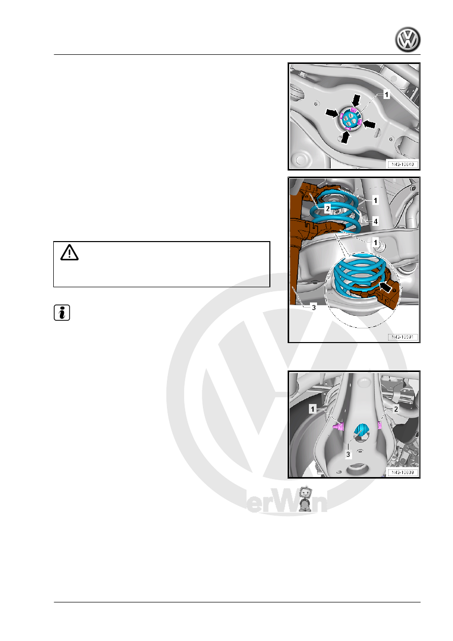
– Press the tabs -arrows- on the assembly aid -1- inward.
– Remove the assembly aid -1- upward.
– Position the - VAS6931- or -VAG1383A- under the transverse

link and push lightly upward.

– Insert the Spring Compressor -3-.
1 - -VAG1752/3A-
2 - -VAG1752/9-
3 - -VAG1752/1-
4 - Spring

WARNING

Make  sure  the  coil  spring  is  seated  correctly  in  the  -

VAG1752/3A- -arrow- (danger of accident).

Note

Use a wrench or a reversible ratchet to tighten the spring com‐

pressor.

– Tension the coil spring.

– Remove the nut -1- and then the bolt -2- for the coupling rod

-3-.

– Remove the nut -1- and then the bolt -2- for the shock absorber

threaded connection.

– Remove the nut -3- and then the bolt -4- for the wheel bearing

housing threaded connection.

WARNING

Hold the -VAG1752/1- with the spring tensioned (risk of acci‐

dent).

– Slowly lower the -VAS6931- or -VAG1383A- under the lower

transverse link, until the -VAG1752/1- with the tensioned

spring can be removed.

Installing
Install in reverse order of removal. Note the following:

– Make sure the washer is not damaged.
– Replace the washer if necessary.
– Install the washer on the coil spring.
The spring start -arrow- must touch the stop of lower spring sup‐

port.
– Install the spring and the spring support.
– Spring seat has a pin on bottom.

– Insert this pin into hole of lower transverse link -arrow-.

– Insert the top of the spring support into the upper spring end.
– The bead on the spring support -arrow- must fit into the coil

spring correctly.

WARNING

Hold the -VAG1752/1- with the spring tensioned (risk of acci‐

dent).

– Push the - VAS6931- or -VAG1383A- under the transverse link

upward.

– Insert the bolt -4- for connecting the wheel bearing housing

and tighten the nut -3-.

– Insert the bolt -2- for connecting the shock absorber and tight‐

en the nut -1-.

– Insert the bolt -2- for the coupling rod -3- and tighten the nut

-1-.

– Release the tension on the spring -4- while positioning the up‐

per spring support onto tab of body.

– Remove the Spring Tensioner -3-.
1 - -VAG1752/3A-
2 - -VAG1752/9-
3 - -VAG1752/1-
4 - Spring

– Insert the assembly aid -1- and push downward.
– The tabs -arrows- must engage.
– For vehicles with a level control system sensor, perform the

basic setting for the wheel damping electronics using the Ve‐

hicle Diagnostic Tester.

Tightening Specifications
♦ Refer to 

⇒ “4.1 Overview - Stabilizer Bar”, page 177

♦ Refer to 

⇒ “5.1 Overview - Transverse Link”, page 181

♦ Refer to

⇒ “6.1 Overview - Suspension Strut, Shock Absorber and

Spring”, page 191

♦ Refer to

⇒ “1.1 Wheel Bolt Tightening Specifications”, page 286


Content   ..  853  854  855  856   ..