Volkswagen Golf / Golf GTI / Golf Variant. Manual - part 815


  Index      Volkswagen     Volkswagen Golf / Golf GTI / Golf Variant - service repair manual 2013 year


Search            copyright infringement  


Content   ..  813  814  815  816   ..


Volkswagen Golf / Golf GTI / Golf Variant. Manual - part 815


❑ Replace after removal

14 - Cover

3.2

Suspension Strut, Removing and Instal‐

ling

Special tools and workshop equipment required
♦ Torque Wrench 1332 40-200Nm - VAG1332-
♦ Spreader Tool - 3424-
♦ Engine and Gearbox Jack - VAS6931-
♦ Engine/Gearbox Jack Adapter - Wheel Hub Support - T10149-
♦ Drive Shaft Remover - T10520-
Removing
– Loosen drive axle bolt on the wheel hub. Refer to

⇒ “6.4 Drive Axle Threaded Connection, Loosening and Tight‐

ening”, page 101

 .

Caution

The wheel bearing must not be under load when the drive axle

threaded connection on the wheel side is loose.
If the wheel bearings are under the load of the vehicle weight,

the wheel bearing will be damaged. This reduces the service

life of the wheel bearings.
The drive axle bolt may be loosened maximum 90° when the

vehicle is standing on its wheels.
Vehicles without a drive axle must not be moved, otherwise the

wheel bearing will be damaged. If a vehicle must be moved,

be sure to note the following:

♦ Install an outer joint in place of the drive axle.
♦ Tighten the outer joint to 120 Nm.

– Loosen the wheel bolts.
– Raise the vehicle.
– Remove the wheel.
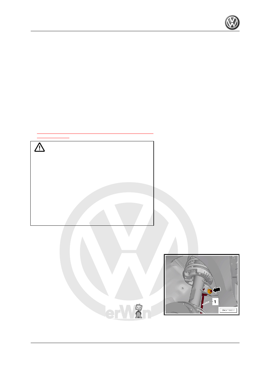
– Remove the nut -arrow- and the coupling rod -1- from the sus‐

pension strut.

– Disengage the wire for the ABS speed sensor from the sus‐

pension strut.

Vehicles with Level Control System Sensor
– Remove the nut -1-.
– Remove the bracket -2- for the Left Front Level Control System

Sensor - G78- or  Right Front Level Control Sensor - G289-

from the control arm -3-.

Continuation for all Vehicles

– Remove the nuts -arrows-.
– Remove the wheel bearing housing with the ball joint from the

control arm.

– Remove the drive axle outer joint from the wheel hub.
If the drive axle cannot be pulled out of the wheel bearing, then

the drive axle can be pushed out of the wheel bearing using the

Drive Shaft Remover - T10520- .

Before using the -T10520- , make sure that the thrust piece -1- is

installed.

Using the -T10520- :
– Secure the -T10520- -1- with three wheel bolts -2- on the wheel

hub, so that the drive axle -3- can be pressed out.

– Follow the specified sequence exactly.
I - Tighten the knurled nut -1- hand-tight.
II - Only turn the bolt -2- using a wrench and press out the drive

axle using the -T10520- .

Note

At the end of the tasks or to set back, the spindles must be brought

back into the original position so that the hydraulic operation can

be used.

– Secure the drive axle to the body using wire.

Caution

The drive axle must not hang down, otherwise the inner joint

will be damaged by over bending.

Vehicles with Adaptive Chassis DCC
– Disconnect the connector -1- from the shock absorber -2-.

Note

If there is moisture in the connector area, blow compressed air on

the contacts on the shock absorber and the connectors.

Continuation for all Vehicles.

– Insert a screwdriver -1- in the brake rotor between the brake

caliper and brake carrier.

– Secure the -VAS6931- using -T10149- -2- to wheel hub with

a wheel bolt.

WARNING

♦ Do not lift or lower the vehicle when the -VAS6931- is un‐

der the vehicle. The vehicle could slip off the hoist.

♦ Do not leave the -VAS6931- under the vehicle any longer

than necessary.

– Disconnect the threaded connection for the wheel bearing

housing/suspension strut -arrow-.

– Insert -3424- into wheel bearing housing slot.

Note

Pay attention that the -3424- is only inserted in the wheel bearing

housing. Only insert it far enough that the suspension strut metal

retainer is not damaged.

– Turn the ratchet 90° and remove it from the -3424- .
– Press the brake rotor toward the suspension strut by hand.
Otherwise the shock absorber tube could tilt in the wheel bearing

housing hole.

– Lower the wheel bearing housing -1- using the -VAS6931- in

the direction of the -arrow-.

– Lower the wheel bearing housing -1- so that the shock ab‐

sorber tube hangs freely -arrow-.

– Fasten the ball joint to the control arm again and secure the

wheel bearing housing to the subframe.

– Remove the -VAS6931- from underneath the -T10149- .

WARNING

♦ Do not leave the -VAS6931- under the vehicle any longer

than necessary.

– Remove the seal from the entire length of the plenum chamber

cover.

– Remove the clips.

– Lift the plenum chamber cover -1- to maximum 60 mm.
a - 60 mm


Content   ..  813  814  815  816   ..