Volkswagen Golf / Golf GTI / Golf Variant. Manual - part 812


  Index      Volkswagen     Volkswagen Golf / Golf GTI / Golf Variant - service repair manual 2013 year


Search            copyright infringement  


Content   ..  810  811  812  813   ..


Volkswagen Golf / Golf GTI / Golf Variant. Manual - part 812


♦ Insert - VAS6779/7-1A-
♦ Hydraulic Press - VAS6178- with Bearing Installer - Wheel

Hub/Bearing Kit Pressure Head - T10205/13-

♦ Press Plate - VW401-
♦ Press Piece - Multiple Use - VW412-

Caution

This procedure contains mandatory replaceable parts. Refer

to component overview prior to starting procedure.

Mandatory Replacement Parts
♦ Nut - Coupling Rod to Stabilizer Bar
♦ Bolts - Subframe to Stabilizer Bar
Replace the Pendulum Support Bonded Rubber Bushing.
– Remove the front noise insulation. Refer to ⇒  Body Exterior;

Rep. Gr.  66 ; Noise Insulation; Overview - Noise Insulation .

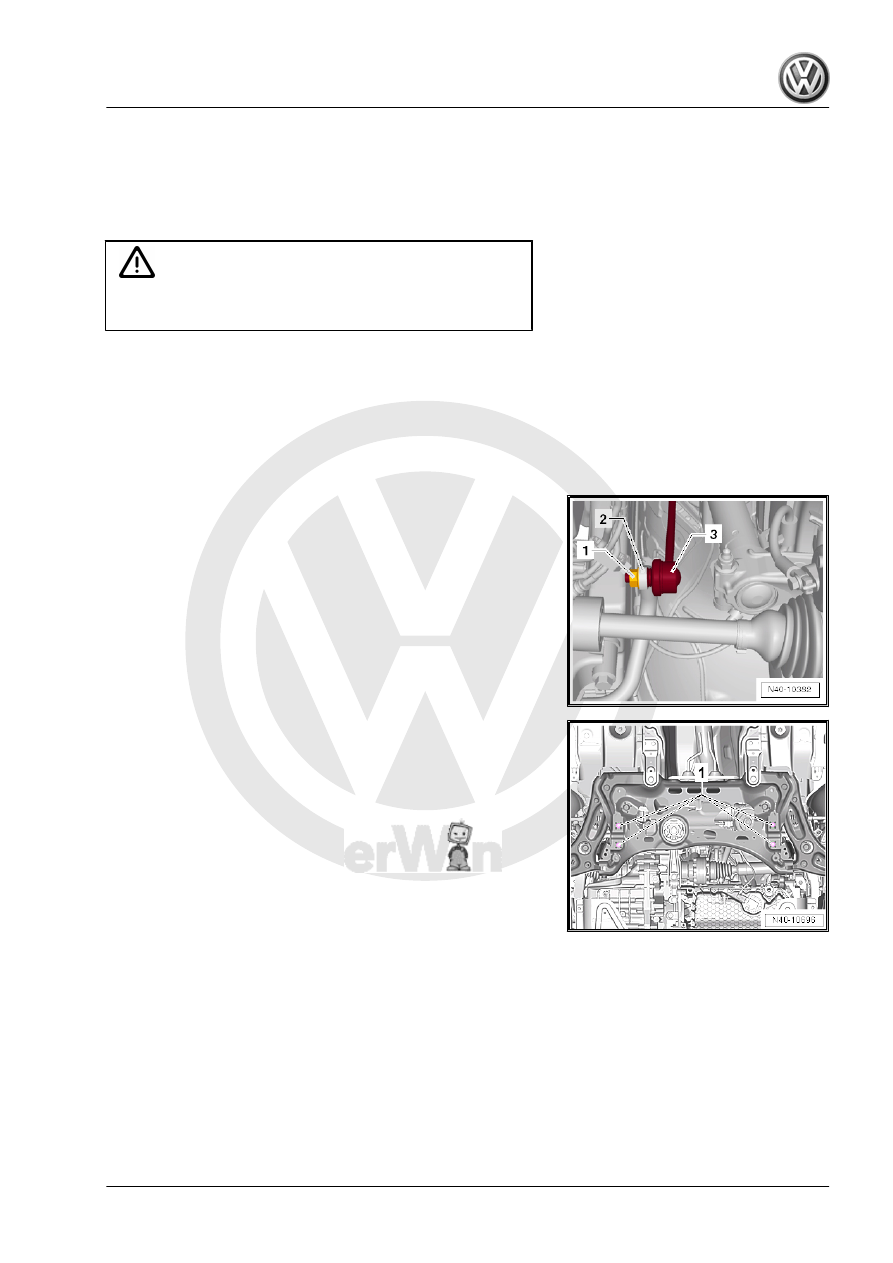
– Remove the hex nut -1- from the right and left coupling rod

-3-.

– Remove the coupling rod -3- from the stabilizer bar -2- on the

left and right sides.

– Remove the stabilizer bar bolts -1-.
• Leave the stabilizer bar in the installed position on the vehicle.
– Remove the pendulum support. Refer to ⇒  Engine Mechani‐

cal, Fuel Injection and Ignition; Rep. Gr.  10 ; Subframe Mount;

Pendulum Support, Removing and Installing or ⇒  Engine Me‐

chanical, Fuel Injection and Glow Plug; Rep. Gr.  10 ; Sub‐

frame Mount; Pendulum Support, Removing and Installing .

Pressing Out the Bonded Rubber Bushing
– Install the Hydraulic Press - Bushing Tool Kit - VAS6779- as

shown in the illustration on the subframe.

– Position the Thrust Piece - VAS6779-1- -1- with the flat side

-arrow- on the bonded rubber bushing in the driving direction.

1 - Thrust Piece - VAS6779/1-
2 - Tube - VAS6779/4-
3 - Thrust Piece - VAS6779/5-
4 - Hydraulic Press - VAS6178- with Bearing Installer - Wheel

Hub/Bearing Kit Pressure Head - T10205/13-
5 - Hexagon Nut - VAS6779/3-
6 - Threaded Rod - VAS6779/2-

– Press out both bonded rubber bushings until the upper bonded

rubber bushing -2- is visible through the opening for the pen‐

dulum support -arrow- in the subframe.

– Perform a visual inspection of the upper bonded rubber bush‐

ing -2- outer race.

• If the upper bonded rubber bushing -2- outer race is deformed,

it must be destroyed through the opening for the pendulum

support -arrow- in the subframe.

– Using a chisel or similar tool -1-, make a break in the upper

bonded rubber bushing -2- outer race.

Note

This work sequence is necessary to prevent tilting of the bonded

rubber bushing outer race in the area of the pendulum support

opening in the subframe.

– Completely press out both bonded rubber bushings at the

same time.

Prepare the Bonded Rubber Bushing Before Pressing In.
– Place the bonded rubber bushings -1 and 2- on top of each

other so the openings -arrows- lay exactly over each other.

– Tighten the bonded rubber bushings -1 and 2- using the orig‐

inal bolt -3- hand tight.

– Place the bonded rubber busing -1- with the bolt head facing

up in the larger diameter of the Funnel - VAS6779/6- -2-.

– Align the bonded rubber bushing -1- in the Funnel -

VAS6779/6- -2-. The bonded rubber bushing opening must

precisely face the recess -arrows- in the Funnel - VAS6779/6-

-2-.

– Press the bonded rubber bushing -3- in the Funnel -

VAS6779/6- as shown in the illustration until stop.

1 - Press Piece - Multiple Use - VW412-
2 - Thrust Piece - VAS6779/5- , the side with the letter »A«

points up

3 - Bonded rubber bushing
4 - Funnel - VAS6779/6-
5 - Tube - VAS6779/4-
6 - Press Plate - VW401-

– Insert the Counter Hold - VAS6779/7- -1- into the subframe.
– Insert the Insert - VAS6779/7-1A- -2- in the pendulum support

opening in the subframe.

– Fasten the Insert - VAS6779/7-1A- onto the Counter Hold -

VAS6779/7- -1-.

– Make sure that the Insert - VAS6779/7-1A- -2- is seated cor‐

rectly in the subframe opening -arrow-.

Installing the Bonded Rubber Bushing
– Install the Threaded Rod - VAS6779/2- -7- in the Counter Hold

- VAS6779/7- -1-.

– Install the Hydraulic Press - Bushing Tool Kit - VAS6779- as

shown in the illustration on the subframe.


Content   ..  810  811  812  813   ..