Volkswagen Golf / Golf GTI / Golf Variant. Manual - part 806


  Index      Volkswagen     Volkswagen Golf / Golf GTI / Golf Variant - service repair manual 2013 year


Search            copyright infringement  


Content   ..  804  805  806  807   ..


Volkswagen Golf / Golf GTI / Golf Variant. Manual - part 806


Caution

All bolts at suspension parts with bonded rubber bushings must

always be tightened in curb weight position (unloaded condi‐

tion).
Bonded rubber bushings have a limited range of motion.
Axle  components  with  bonded  rubber  bushings  must  be

brought into the position they will be in during driving before

tightening (curb weight position).
Otherwise, the bonded rubber bushing will be stressed result‐

ing in a shortened service life.

By raising the axle on one side using the Engine and Gearbox

Jack - VAS6931- and Engine/Gearbox Jack Adapter - Wheel Hub

Support - T10149- , this position can be simulated on the hoist.
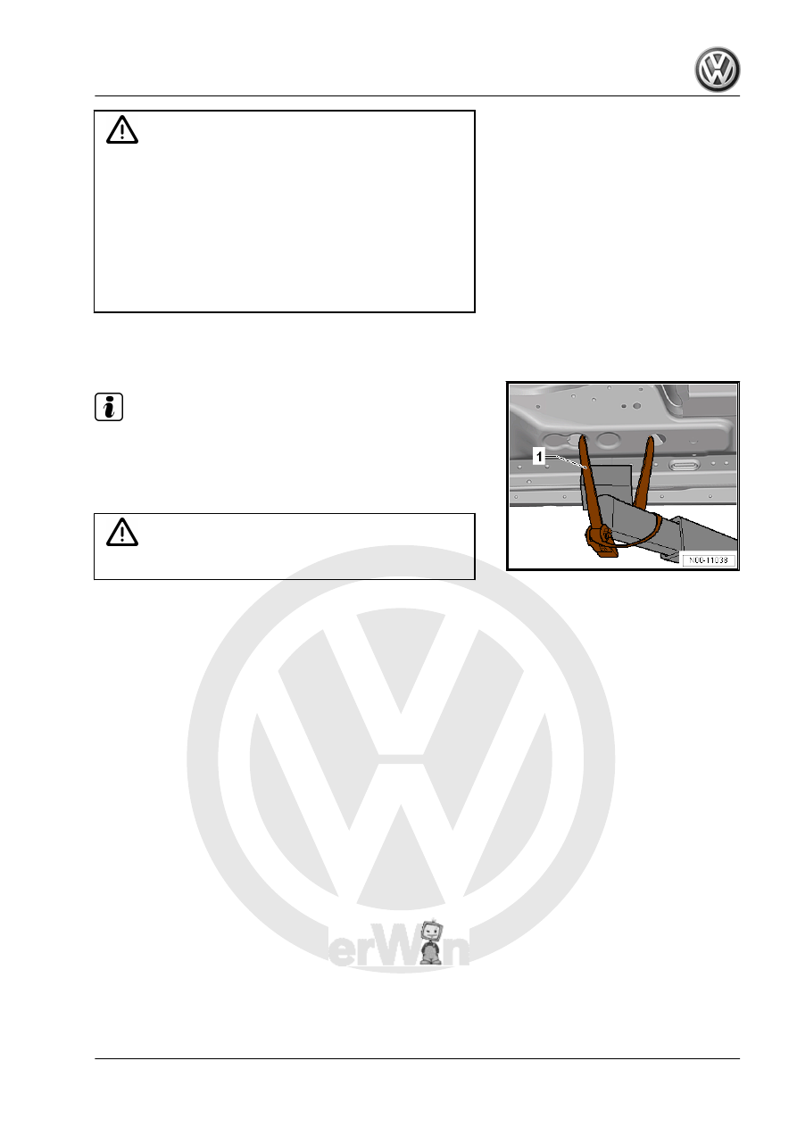
Note

Before lifting the axle on one side, the vehicle must be secured

on both sides to the lift arms of the lift using Tensioning Strap -

T10038- .

1 - Tensioning Strap - T10038-

WARNING

The vehicle could fall off the hoist if it is not secured.

– Turn the wheel hub until one of the holes for the wheel bolts

is on top.

– Install Engine/Gearbox Jack Adapter - Wheel Hub Support -

T10149- with wheel bolt.

Note

Tightening of the respective bolts/nuts must then only occur after

dimension -a- between the wheel hub center and the lower edge

of wheel housing has been attained.

Dimension -a- is dependent on standing height of installed sus‐

pension:

Chassis 

1)

Standing Height -a- in mm

Basic (G01/G02/G07/G18/G22

+2UA)

385 ± 10 mm

Sport (G01/G02/G07 +2UC,

G21)

370 ± 10 mm

Raised (G01/G02 +2UF)

400 ± 10 mm

DCC (G03)

375 ± 10 mm

GTI (G06+2UC/ G06 + 2UJ/

G04 + 2UM)

370 ± 10 mm

GTI heavy duty suspension

(G06 + 2UN)

385 ± 10 mm

1)

 The suspension that the vehicle is equipped with is indicated

on the vehicle data plate. The suspension is indicated by a PR

number. Allocation of the PR number according to the suspen‐

sion.
– Lift the wheel bearing housing using the engine/gearbox jack

until dimension -a- is reached.

WARNING

♦ Do not lift or lower the vehicle when the Engine and Gear‐

box Jack - VAS6931- is below the vehicle.

♦ Do not leave the engine/gearbox jack under the vehicle

any longer than necessary.

– Tighten the bolts and nuts.
– Lower the wheel bearing housing.
– Remove the Engine and Gearbox Jack - VAS6931- from under

the vehicle.

– Remove the Engine/Gearbox Jack Adapter - Wheel Hub Sup‐

port - T10149-

4

Disposal

⇒ “4.1 Front Shock Absorbers, Venting and Emptying”,

page 11
⇒ “4.2 Rear Shock Absorbers, Venting and Emptying”,

page 12

4.1

Front Shock Absorbers, Venting and

Emptying

⇒ “4.1.1 Front Shock Absorbers, Venting and Emptying, Standard

Shock Absorber”, page 11
⇒ “4.1.2 Front Shock Absorbers, Venting and Emptying, DCC

Shock Absorber”, page 12

4.1.1

Front Shock Absorbers, Venting and

Emptying, Standard Shock Absorber

– Secure the gas-filled shock absorber vertically in vise, with

piston rod facing down.

WARNING

Wear protective eyewear while drilling.

– Drill a 3 mm hole -A- through the shock absorber outer tube.

Note

Gas escapes when drilling.

– Continue drilling until the tube inside is drilled through (ap‐

proximately 25 mm deep).

– Drill a second 6 mm hole -B- through the outer and inner shock

absorber tubes.

– Hold the shock absorber over an appropriate container for

catching oil and move the piston rod repeatedly through the

entire stroke until no more oil flows out.

4.1.2

Front Shock Absorbers, Venting and

Emptying, DCC Shock Absorber

– Tension the gas-filled shock absorber vertically in the vise.

WARNING

Wear protective eyewear while drilling.

– Drill a 3 mm hole -A- through the shock absorber outer tube.

Note

Gas escapes when drilling.

– Continue drilling until the tube inside is drilled through (ap‐

proximately 25 mm deep).

– Drill a second 6 mm hole -B- through the outer and inner shock

absorber tubes.

– Hold the shock absorber over an appropriate container for

catching oil and move the piston rod repeatedly through the

entire stroke until no more oil flows out.

4.2

Rear Shock Absorbers, Venting and

Emptying

⇒ “4.2.1 Rear Shock Absorbers, Venting and Emptying, Standard

Shock Absorber”, page 12
⇒ “4.2.2 Rear Shock Absorbers, Venting and Emptying, DCC

Shock Absorber”, page 13

4.2.1

Rear Shock Absorbers, Venting and

Emptying, Standard Shock Absorber

– Tension the gas-filled shock absorber vertically in the vise.

WARNING

Wear protective eyewear while drilling.

– Drill a 3 mm hole -A- through the shock absorber outer tube.

Note

Gas escapes when drilling.

– Continue drilling until the tube inside is drilled through (ap‐

proximately 25 mm deep).

– Drill a second 6 mm hole -B- through the outer and inner shock

absorber tubes.

– Hold the shock absorber over an appropriate container for

catching oil and move the piston rod repeatedly through the

entire stroke until no more oil flows out.


Content   ..  804  805  806  807   ..