Volkswagen Golf / Golf GTI / Golf Variant. Manual - part 795
– Disconnect the bat‐
tery. Refer to ⇒ Elec‐
trical Equipment;
Rep. Gr. 27 ; Battery;
Battery, Disconnect‐
ing and Connecting .
– Remove the battery.
Refer to ⇒ Electrical
Equipment; Rep. Gr.
27 ; Battery; Battery,
Removing and Instal‐
ling .
– Remove the engine
cover. Refer to ⇒ En‐
gine Mechanical,
Fuel Injection and Ig‐
nition; Rep. Gr. 10 ;
Engine Cover; En‐
gine Cover, Remov‐
ing and Installing .
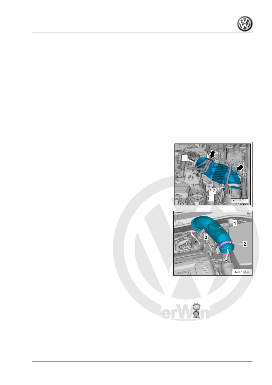
Diesel Vehicles
– Unclip the vacuum line from the air guide hose.
– Open the clamps -1 and 2-.
– Remove the air guide hose.
– Remove the air filter housing. Refer to ⇒ Engine Mechanical,
Fuel Injection and Glow Plug; Rep. Gr. 23 ; Air Filter; Air Filter
Housing, Removing and Installing .
Vehicles with 2.0 L Gasoline Engine
– Open the clamps -2 and 3-.
– Remove the air guide hose -1-.
– Remove the air filter housing. Refer to ⇒ Engine Mechanical,
Fuel Injection and Ignition; Rep. Gr. 24 ; Air Filter; Air Filter
Housing, Removing and Installing .