Volkswagen Golf / Golf GTI / Golf Variant. Manual - part 759
 

  Index      Volkswagen     Volkswagen Golf / Golf GTI / Golf Variant - service repair manual 2013 year


Search            copyright infringement  


Content   ..  757  758  759  760   ..


Volkswagen Golf / Golf GTI / Golf Variant. Manual - part 759


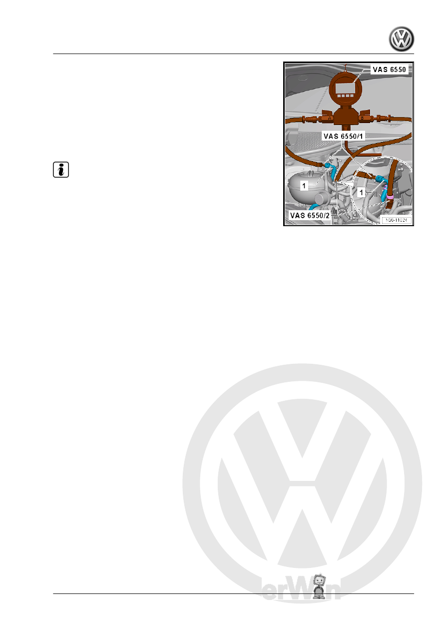
– Connect the Pressure Tester Kit - Hose 2 - VAS6550/2- be‐

tween the fuel line from the fuel tank and the shut-off valve

-B- on the Pressure Tester Kit - VAS6550- .

– Connect the Pressure Tester Kit - Hose 1 - VAS6550/1- be‐

tween the fuel line leading to the engine -1- and the shut-off

valve -A- on the Pressure Tester Kit - VAS6550- .

Test sequence:
– Connect the Vehicle Diagnostic Tester .
– Select the fuel pump output diagnostic test mode in OBD.

Note

♦

The fuel pump is now activated to build up the fuel pressure.

♦

If the output diagnostic test mode is performed several times

in succession, it may be necessary to briefly start the motor

before repeating the output diagnostic test mode.

– Read the fuel pressure on the pressure gauge.
• Specified value: greater than or equal to 4.0 bar
– End the OBD and turn off the ignition.
– Observe the decrease in pressure on the pressure gauge. Af‐

ter 10 minutes the pressure must not drop more than approx‐

imately 1 bar.

If the pressure drops:
– Check all of the fuel lines for leaks and damage.

If no faults can be found:
– Make sure that the drain valve -C- on the Pressure Tester

-1- is closed.

– The shut-off valves -A- and -B- on the Pressure Tester Kit

-1- are opened.

– Activate the fuel pump using the output diagnostic test mode

to build the fuel pressure.

– Close the shut-off valve -A- on the pressure gauge immedi‐

ately after the pressure has been reached. The lever is per‐

pendicular to the flow direction.

If the pressure drops again (Leak on fuel tank side):
Proceed as follows to check residual pressure on the fuel delivery

unit. Refer to 

⇒ page 102

 .

If the pressure now stops decreasing (leak on the engine side):

Note

Check for the leak on the engine-side. Repeat the residual pres‐

sure check. Close the shut-off valve -B- this time to determine if

there actually is a leak on the engine side.

If there is a leak on the engine side:
– Check the fuel lines externally for leaks.
– Check the fuel rail and the fuel injectors externally for leaks.

Refer to ⇒  Rep. Gr.  24 ; Fuel Injectors; Overview - Fuel Rail

with Fuel Injectors .

If no error can be found:
– Check the fuel injectors for leaks. Refer to ⇒  Rep. Gr.  24 ;

Fuel Injector; Fuel Injectors, Checking .

Residual Pressure in Fuel Delivery Unit, Checking:
Golf Sportsvan:
– Remove the right rear seat. Refer to ⇒  Body Interior; Rep. Gr. 

72 ; Rear Seats; Bench Seat / Single Seat, Removing and In‐

stalling .

– Partially loosen the cover -1- in the carpet at the separating

line -arrow-.

– Do not separate the cover completely from the carpet so that

later it will be installed correctly.

– Only loosen so far that the cover can be folded up.
– Fold up the cover in the -direction of the arrow-.
Golf and Golf wagon:
– Remove the rear bench seat. Refer to ⇒  Body Interior; Rep.

Gr.  72 ; Rear Seats; Bench Seat / Single Seats, Removing

and Installing .

Continuation for All Vehicles:
– Unclip the sealing flange cover -1- at the tabs -arrows- using

the Trim Removal Wedge - 3409- .

– Unclip the grommet -1- downward out of the cover -2-.
– Guide the cover -2- on the wiring harness -3- toward the rear.

– Pull the fuel line -1- off the flange. Disconnect the connector

couplings. Refer to

⇒ “4.1 Connector Couplings, Disconnecting”, page 62

 .

WARNING

The fuel line is under pressure.
Fuel poses a risk of injury to the eyes and skin.
Wear protective eyewear and protective clothing to avoid injury

and contact with skin. Place a cleaning cloth around the con‐

nection  point  before  loosening  hose  connections.  Carefully

open the connection point to release the pressure.

– Connect the Pressure Tester Kit - VAS6550- to the fuel deliv‐

ery unit -1- using the Pressure Tester Kit - Adapter Set - Hose

4 - VAS6550/3-4- .

– Connect the Pressure Tester Kit - Adapter Set - Hose 3 -

VAS6550/3-3- between the Pressure Tester Kit - VAS6550-

and the fuel line -2-.

– Pull on the connector couplings to check them for secure fit.

– Make sure that the drain valve -C- on the Pressure Tester

-1- is closed.

– The shut-off valves -A- and -B- on the Pressure Tester Kit

-1- are opened.

– Activate the fuel pump using the output diagnostic test mode

to build the fuel pressure.

– Close the shut-off valve -B- on the pressure gauge immedi‐

ately after the pressure has been reached. The lever is per‐

pendicular to the flow direction.

– Repeat the residual pressure check. Refer to 

⇒ page 101

 .

If the pressure no longer decreases:
– Check the fuel line for leaks.

If the pressure drops again:
– Open the fuel delivery unit -1-. Refer to

⇒ “2.2 Fuel Delivery Unit/Fuel Level Sensor, Removing and

Installing”, page 52

 .

– Make sure all hose connections -arrows- are connected.
– Check the fuel lines for leaks and damage.
If no error can be found:
– If the pressure retaining valve in the fuel delivery unit is faulty,

replace the fuel delivery unit. Refer to

⇒ “2.2 Fuel Delivery Unit/Fuel Level Sensor, Removing and

Installing”, page 52

 .

8.1.7

Fuel Delivery Rate, Checking

Special tools and workshop equipment required
♦ Trim Removal Wedge - 3409-
♦ Pressure Tester Kit - VAS6550-
♦ Pressure Tester Kit - Adapter Set - Hose 3 - VAS6550/3-3-
♦ Pressure Tester Kit - Adapter Set - Hose 4 - VAS6550/3-4-
♦ Pressure Regulator Valve - VAS6550/4-
♦ Connector Test Set - VAG1594D-
♦ Multimeter, for example Analog/Digital Multimeter - FLU83III-
♦ Injection Rate Comparison Meter Kit - Remote Cable -

VAG1348/3A-

♦ Vehicle Diagnostic Tester - Test Adapter - 5 Pin - VAS5565-
♦ Vehicle Diagnostic Tester
♦ Measuring container, greater than three liters


Content   ..  757  758  759  760   ..