Volkswagen Golf / Golf GTI / Golf Variant. Manual - part 674


  Index      Volkswagen     Volkswagen Golf / Golf GTI / Golf Variant - service repair manual 2013 year


Search            copyright infringement  


Content   ..  672  673  674  675   ..


Volkswagen Golf / Golf GTI / Golf Variant. Manual - part 674


– Turn the crankshaft with the socket SW 24 on the vibration

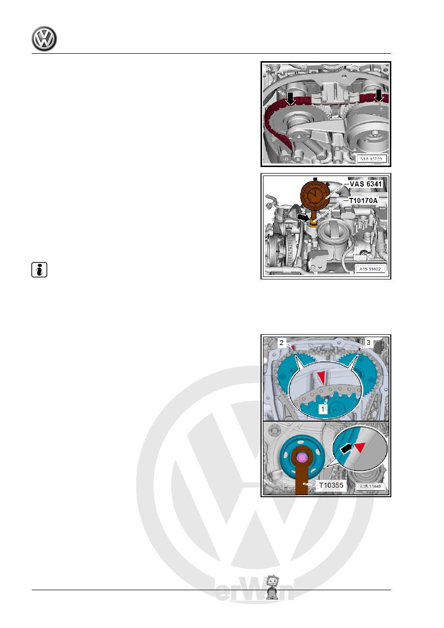
damper in the direction of the engine rotation until the mark‐

ings -arrows- are almost on top.

– Remove the spark plug from cylinder 1.

– Install the Dial Gauge Adapter - T10170/A- all the way into the

spark plug thread.

– Insert the Dial Gauge - 0-10mm - VAS6341- using the Exten‐

sion - T10170A/1- until stop and secure with the locking nut

-arrow-.

– Turn the crankshaft slowly to maximum dial reading in the di‐

rection of the engine rotation. When the maximum dial reading

is reached (Bottom Dead Center (BDC) of the meter) position

the piston at »Top Dead Center (TDC)«.

Note

Use a ratchet with a 24 mm socket to turn the vibration damper.

If the crankshaft was turned past “TDC”, turn the crankshaft

two more turns in the direction of the engine rotation. Do not

turn the engine in the opposite direction of the engine rotation.

• The notch on the vibration damper must line up with the arrow

marking on the timing chain lower cover -arrow-.

• The markings -1- on the camshaft chain sprockets must be

opposite the markings -2 and 3- on the cylinder head.

4

Valvetrain

⇒ “4.1 Overview - Valvetrain”, page 133
⇒ “4.2 Camshaft, Removing and Installing”, page 136
⇒ “4.3  Camshaft Adjustment Valve 1 N205 , Removing and In‐

stalling”, page 160
⇒ “4.4  Camshaft Adjustment Valve 1 N205 and Exhaust Cam‐

shaft Adjustment Valve 1 N318 , Removing and Installing”, page

161
⇒ “4.5 Sliding Bar Ball, Installing”, page 162
⇒ “4.6 Valve Stem Seals, Removing and Installing”, page 163

4.1

Overview - Valvetrain

Note

The cylinder head and the cylinder head cover must be re‐

placed together.

Do not start the engine for approximately 30 minutes after in‐

stalling the camshafts. The hydraulic equalization elements

must seat themselves (otherwise the valves will crash into the

pistons).

After working on the valvetrain and lifters, carefully rotate the

crankshaft by hand at least two full revolutions before starting

to be sure that valves do not strike the pistons.

Replace the gaskets and seals.

After performing work on the chain drive the adaptation value

in the Engine Control Module (ECM) must be adapted. To do

this turn on the ignition and select the following menu items on

the Vehicle Diagnostic Tester :

01 - Engine Electronics

Guided Functions

01 - Adaptation After Repair Work On the Chain

Drive

1 - Exhaust Valve

❑ Do not rework, only lap‐

ping is permitted

❑ Valve dimensions. Re‐

fer to

⇒ “5.3 Valve Dimen‐

sions”, page 170

 .

❑ Valve guides, checking.

Refer to

⇒ “5.1 Valve Guides,

Checking”, page 170

 .

2 - Cylinder Head
3 - Valve Stem Seal

❑ Replacing. Refer to

⇒ “4.6 Valve Stem

Seals, Removing and

Installing”, page 163

 .

4 - Valve Spring
5 - Valve Spring Retainer
6 - Valve Retainers
7 - Hydraulic Adjusting Ele‐

ment

❑ Do not interchange
❑ Lubricate contact sur‐

face

8 - Clip

❑ For hydraulic adjuster

9 - Roller Rocker Lever

❑ Removing and instal‐

ling. Refer to

⇒ “4.2 Camshaft, Re‐

moving and Installing”,

page 136

 .

❑ Mark the installed position for installation later
❑ Check roller for easy movement
❑ Lubricate the running surfaces before installing

10 - Exhaust Camshaft

❑ Removing and installing. Refer to 

⇒ “4.2 Camshaft, Removing and Installing”, page 136

 .

❑ Check radial clearance using Plastigage

®

 (roller rocker lever removed)

❑ Radial clearance: 0.024 to 0.066 mm
❑ Run-out: maximum 0.04 mm

11 - Spring

❑ No replacement part

12 - Ball

❑ For sliding bar
❑ Installing. Refer to 

⇒ “4.5 Sliding Bar Ball, Installing”, page 162

 .

13 - Cylinder Head Cover

❑ With integrated camshaft bearings
❑ Clean sealing surface, reworking is not permitted.
❑ Remove old sealant residue.

14 - Bolt

❑ Replace after removing
❑ Loosening. Refer to 

⇒ Fig. ““Loosening the Cylinder Head Cover”“ , page 135

❑ Tightening sequence. Refer to 

⇒ Fig. ““Cylinder Head Cover Tightening Sequence”“ , page 135

15 - Intake Camshaft

❑ Removing and installing. Refer to 

⇒ “4.2 Camshaft, Removing and Installing”, page 136

 .

❑ Check radial clearance using Plastigage

®

 (roller rocker lever removed)

❑ Radial clearance: 0.024 to 0.066 mm
❑ Run-out: maximum 0.04 mm

16 - Alignment Pins
17 - Alignment Pins
18 - Intake Valve

❑ Do not rework, only lapping is permitted
❑ Valve dimensions. Refer to 

⇒ “5.3 Valve Dimensions”, page 170

 .

❑ Valve guides, checking. Refer to 

⇒ “5.1 Valve Guides, Checking”, page 170

 .

Loosening the Cylinder Head Cover
– Loosen the cylinder head cover in the order -1 through 6-.

Cylinder Head Cover Tightening Sequence
– Replace the bolts after removing them.

Step

Bolts

Tightening Specification/Additional

Turn

1.

-1- through -6-

Install hand-tight in several stages

2.

-1- through -6-

8 Nm

3.

-1- through -6-

Turn an additional 90°.

Note

Pay attention that the cylinder head cover is not tilted.


Content   ..  672  673  674  675   ..