Volkswagen Golf / Golf GTI / Golf Variant. Manual - part 670
14 - Three Stage Chain Sprocket
❑ Crankshaft
❑ Installed position. Refer to
⇒ Fig. ““Three Stage Chain Sprocket - Installed Position”“ , page 116
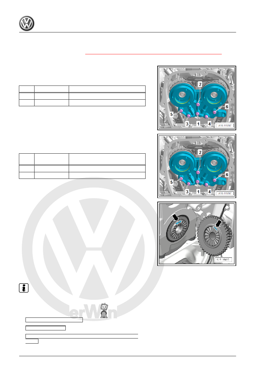
Tightening Specification and Sequence for Bearing Bracket with
Steel Bolts
– Tighten the bolts in steps in the sequence shown:
Step
Bolts
Tightening Specifications
1.
-1-
3 Nm
2.
-1 to 6-
9 Nm
Tightening Specification and Sequence for Bearing Bracket with
Aluminum Bolts
– Tighten the bolts in steps in the sequence -1 to 6-:
Step
Bolts
Tightening Specification/Additional
Turn
1.
-1- through -6-
4 Nm
2.
-1- through -6-
180° additional turn
Three Stage Chain Sprocket - Installed Position
• Both surfaces must -arrows- must line up across from each
other.
3.2
Overview - Balance Shaft Drive Chain
Note
♦
After performing work on the chain drive the adaptation value
in the engine control module must be adapted. To do this turn
on the ignition and select the following menu items on the Ve‐
hicle Diagnostic Tester :
♦
01 - Engine electronics
♦
Guided functions
♦
01 - Adaptation after repair work on the chain
drive