Volkswagen Golf / Golf GTI / Golf Variant. Manual - part 596


  Index      Volkswagen     Volkswagen Golf / Golf GTI / Golf Variant - service repair manual 2013 year


Search            copyright infringement  


Content   ..  594  595  596  597   ..


Volkswagen Golf / Golf GTI / Golf Variant. Manual - part 596


– Press the outer race/tapered roller bearing and the selected

shim (1.175 mm in the example) into the transmission housing

using the Press Piece - Multiple Use - VW510- .

– Install the transmission housing and tighten the bolts.
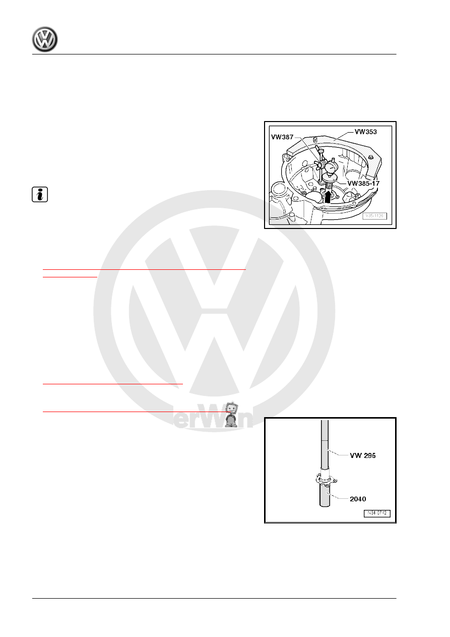
Checking Measurement

– Install the measuring device and the dial gauge.
– Turn the input shaft so that the tapered roller bearings settle.
– Press the input shaft in direction of -arrow-.
– Bearing play must be between a minimum 0.01 to maximum

0.09 mm.

Note

The adjustment is OK if it is not possible to measure the bearing

play and yet the input shaft still have a noticeable play and it easy

to turn.

Tightening Specifications
♦ Refer to

⇒ “5.4 Overview - Transmission Housing and Selector Mech‐

anism”, page 95

 .

1.4

Input Shaft Seal, Replacing

Special tools and workshop equipment required
♦ Bearing/Bushing Installer - Multiple Use - VW295-
♦ Bearing/Bushing Installer - Multiple Use - VW295A-
♦ Press Piece - Multiple Use - VW454-
♦ Press Piece - Front Control Arm - 2040-
– Remove the transmission. Refer to

⇒ “2.1 Transmission, Removing”, page 67

 .

– Remove the clutch release lever with the release bearing and

guide sleeve. Refer to

⇒ “1.16 Clutch Release Mechanism, Servicing”, page 35

 .

– Drive seal out of guide sleeve.

– Fill the space between the sealing and dust lip -arrow- halfway

with Sealing Grease - G 052 128 A1- .

– Coat the outer circumference of the seal lightly with transmis‐

sion fluid.

– Install the seal all the way into the guide sleeve.
– Install the clutch release lever with the release bearing and

guide sleeve. Refer to

⇒ “1.16 Clutch Release Mechanism, Servicing”, page 35

 .

– Install the transmission. Refer to

⇒ “2.2 Transmission, Installing”, page 77

 .

Tightening Specifications
♦ Refer to

⇒ “1.4 Overview - Clutch Release Mechanism”, page 18

2

Output Shaft

⇒ “2.1 Overview - Output Shaft”, page 154
⇒ “2.2 Output Shaft, Disassembling and Assembling”,

page 158
⇒ “2.3 Output Shaft, Adjusting”, page 166

2.1

Overview - Output Shaft

Note

Disassemble the output shaft as follows: place the separating device under the 2nd gear wheel -item 21-

⇒ Item 21 (page 157)

 and remove it as described. Refer to

⇒ Fig. ““Removing the 3rd/4th Gear Synchronizer Hub/Locking Collar, 2nd Gear Wheel, 3rd and 4th Gear

with Output Shaft Needle Bearing Sleeve”“ , page 160

 . Remove the locking ring -item 17-

⇒ Item 17 (page 156)

 . Remove the locking collar and the 1st/2nd gear synchronizer hub as described.

Refer to

⇒ Fig. ““Removing the Locking Collar with the Synchronizer Hub and Bearing Mount”“ , page 160

 .

Consult the Parts Catalog and the Technical data when installing new gear wheels or a new output shaft.

Refer to 

⇒ “4 Technical Data”, page 6

 .

Replace both tapered roller bearings together.

Wearing safety gloves, warm the inner race/tapered roller bearing, the gear wheels and the synchronizer

hubs to approximately 100 °C (212 °F) using an Inductive Heat Unit - VAS6414- before installing them.

1 - Nut

❑ 4 nuts for the bearing

mount

❑ Replace after removing
❑ Tightening specifica‐

tion. Refer to

⇒ “5.6 Overview - Input

Shaft, Output Shafts,

Differential, Gearshift

Rods”, page 97

 .

2 - Clutch Housing
3 - Shim

❑ For the output shaft
❑ Adjustment overview.

Refer to

⇒ “3 Adjustment Over‐

view”, page 198

 .

4 - Small Outer Race/Tapered

Roller Bearing

❑ Removing. Refer to

⇒ Fig. ““Remove the

Small Outer Race/Ta‐

pered Roller Bearing”“ ,

page 159

 .

❑ Installing. Refer to

⇒ Fig. ““Installing the

Small Outer Race/Ta‐

pered Roller Bearing”“ ,

page 159

5 - Small Inner Race/Tapered

Roller Bearing

❑ Removing. Refer to

⇒ Fig. ““Removing the

Inner Race/Small Ta‐

pered Roller Bearing”“ ,

page 159

❑ Installing. Refer to 

⇒ Fig. ““Installing the Inner Race/Small Tapered Roller Bearing”“ , page 160

6 - Output Shaft

❑ Adjusting. Refer to 

⇒ “2.3 Output Shaft, Adjusting”, page 166

 .

7 - Inner Race/Tapered Roller Bearing

❑ Removing. Refer to 

⇒ Fig. ““Removing the Inner Race/Large Tapered Roller Bearing”“ , page 160

❑ Installing. Refer to 

⇒ Fig. ““Installing the Inner Race/Large Tapered Roller Bearing”“ , page 161

8 - Seal

❑ Place the four seals on the bearing mount bolts.
❑ Replace after removing

9 - Bearing Mount

❑ With the large outer race/tapered roller bearing and bolts
❑ Replace the outer race only together with the large tapered roller bearing and bearing mount

10 - Thrust Washer

❑ The collar on the thrust washer faces the tapered roller bearing

11 - 1st Gear Wheel
12 - Needle Bearing

❑ For 1st gear


Content   ..  594  595  596  597   ..