Volkswagen Golf / Golf GTI / Golf Variant. Manual - part 563
Installing
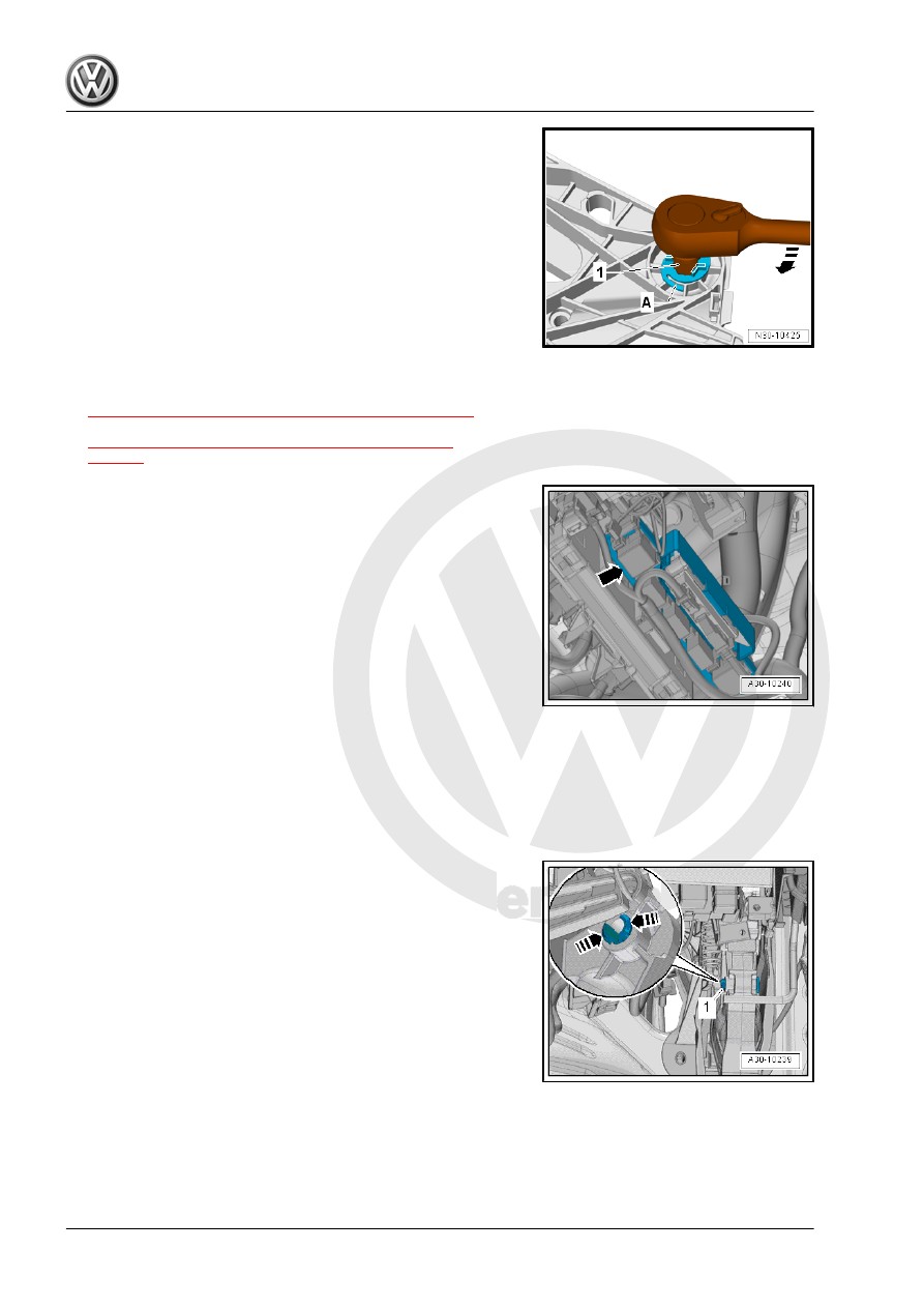
Install in reverse order of removal. Note the following:
-1- = 14 mm internal socket wrench
A 14 mm hex socket wrench can also be used instead of a 14 mm
internal socket wrench.
• Replace bearing axle after removing.
– Press on the clutch pedal a little and push the new bearing
axle through all the way.
– Turn the bearing axle all the way to the right, in direction of
-arrow-.
• The retainers -A- must engage audibly.
– Install the return spring (Refer to
⇒ “1.8 Return Spring, Removing and Installing”, page 23
.)
or install the over-center spring. Refer to
⇒ “1.7 Over-Center Spring, Removing and Installing”,
.
– Install bracket -arrow- with Parking Aid Control Module -
J446- . Refer to ⇒ Electrical Equipment; Rep. Gr. 94 ; Parking
Aid; Overview - Parking Aid .
1.6
Bearing Bushing, Removing and Instal‐
ling
Removing
Disconnect the battery ground cable. Refer to ⇒ Electrical Equip‐
ment; Rep. Gr. 27 ; Battery; Battery, Disconnecting and Con‐
necting .
– Press together the retainers in direction of -arrows- and re‐
move the studs -1- to the right side.
– Turn the valve fitter such that the openings -1- or pin -2- are
visible.
The openings -1- and the pin -2- face in the same direction.