Volkswagen Golf / Golf GTI / Golf Variant. Manual - part 514
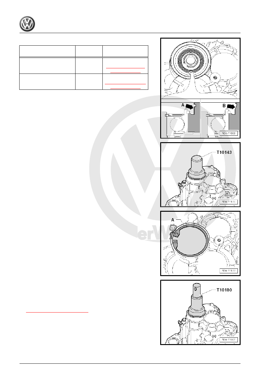
Allocation
Mounting Area for the Cov‐
er
Cover
Installation
-Arrow A- is at vertical
Made of
metal
Refer to
-Arrow B- is at an angle
Plastic
Refer to
Metal Cover
– Install the cap all the way into the transmission housing.
– Secure the cap with the locking ring -A-.
Plastic Cover
– Install the cap all the way into the transmission housing.
Continuation for All
• Always pay attention to the cover allocation. Refer to
⇒ Fig. ““Allocation”“ , page 128
.
• Leaks in the case of incorrect installation.
• For the correct cap. Refer to the Parts Catalog.