Volkswagen Golf / Golf GTI / Golf Variant. Manual - part 479


  Index      Volkswagen     Volkswagen Golf / Golf GTI / Golf Variant - service repair manual 2013 year


Search            copyright infringement  


Content   ..  477  478  479  480   ..


Volkswagen Golf / Golf GTI / Golf Variant. Manual - part 479


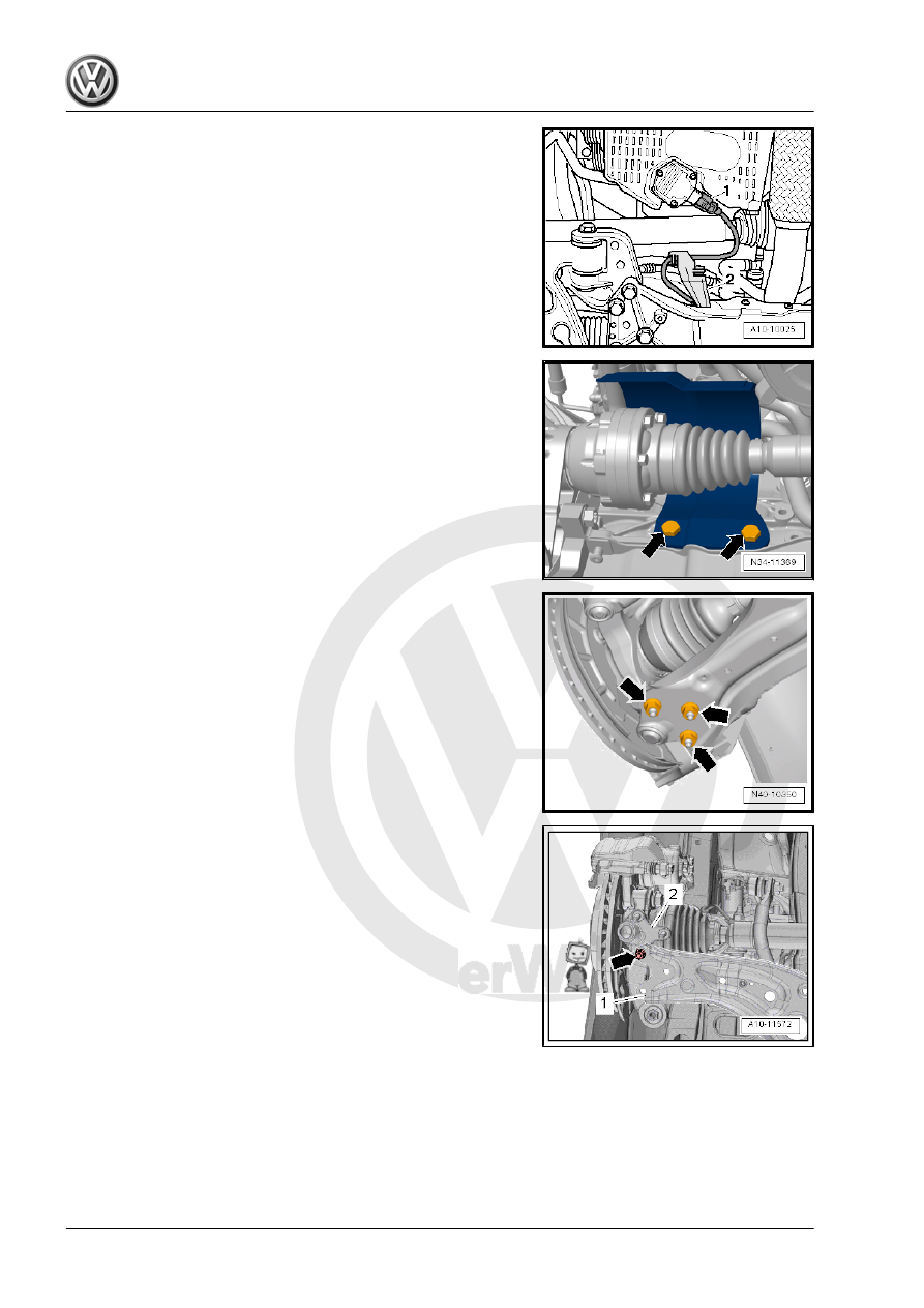
– Disconnect the connector -1- from the Oil Level Thermal Sen‐

sor - G266- , if equipped.

– If equipped, remove the heat shield above the right drive axle

-arrows-.

– Remove the right drive axle from the transmission. Refer to ⇒ 

Suspension, Wheels, Steering; Rep. Gr.  40 ; Drive Axle; Drive

Axle, Removing and Installing .

– Remove the nuts -arrows- on the right ball joint.
– Remove the nut from the bracket for the Right Front Level

Control Sensor - G289- if equipped.

– Disengage the right ball joint from the control arm.

– Fasten the right ball joint -2- on the control arm -1- with a nut

-arrow-, as shown in the illustration.

– Secure the right drive axle to the suspension strut using a

Tensioning Strap - T10038- .

Do not damage the surface of the shaft.
– Place the Used Oil Collection and Extraction Unit -

SMN372500- or Drip Tray under the transmission.

– Remove the right transmission flange shaft using the Socket

And Extended Bit - T10107A- .

The bolt has a 6 mm inner hex socket. The bolt can also be re‐

moved and installed using Long Hex Socket - VAG1669- .

– To remove and install the flange shaft, install 2 bolts into the

flange and counterhold it using a pry bar.

– Remove the flange shaft.
– Pry out the sealing ring.
Installing
Install in reverse order of removal. Note the following:
– Lightly oil new seal on outer circumference.

– Fill the space between the sealing and dust lip -arrow- halfway

with Sealing Grease - G 052 128- .

– Install the seal all the way in without tilting it.

Note

Press the flange shaft against the transmission so that the bolt in

the threaded piece of the differential touches.

– Insert the flange shaft and secure it with bolts.
– Install the ball joint. Refer to ⇒  Suspension, Wheels, Steering;

Rep. Gr.  40 ; Lower Control Arm and Ball Joint; Overview -

Lower Control Arm and Ball Joint .

– Fasten the drive axle to the flange shaft. Refer to ⇒  Suspen‐

sion, Wheels, Steering; Rep. Gr.  40 ; Drive Axle; Drive Axle,

Removing and Installing .

– Install the heat shield over the right drive axle, if equipped.

Refer to ⇒  Suspension, Wheels, Steering; Rep. Gr.  40 ; Drive

Axle; Drive Axle, Removing and Installing .

– Check the fluid level and fill if necessary. Refer to

⇒ “9.1 Transmission Fluid Level, Checking”, page 113

 .

– Install the noise insulation. Refer to ⇒  Body Exterior; Rep. Gr. 

66 ; Noise Insulation; Overview - Noise Insulation .

Tightening Specifications
♦ Flange shaft to transmission. Refer to

⇒ “1.1 Component Location Overview - Seals”, page 128

 .

2

Special Tools

Special tools and workshop equipment required
♦ Used Oil Collection and Extraction Unit - SMN372500-

♦ Tensioning Strap - T10038-

♦ Socket And Extended Bit - T10107A-

♦ Slide Hammer Set - VW771-


Content   ..  477  478  479  480   ..